Every CNC machining center, lathe, and machining cell in your shop shares one quiet dependency: clean, dry, correctly pressurized compressed air. On a modern Doosan machine tools turning center or vertical machining center, compressed air does far more than blow chips off the table — it actuates the pneumatic spindle and tailstock, powers the ATC (automatic tool changer) arm, purges the spindle taper between tool changes, pressurizes the machine enclosure, and lubricates the guideway way-oil system. When that air supply is undersized, wet, or unstable, the results are exactly the kind of failures that show up on a used machinery purchase or a production-line downtime report: tool-change mispositioning, spindle taper contamination, solenoid valve failures, and intermittent alarms that take weeks to chase down.
This guide is written for shop owners and maintenance teams who run a mix of new and used machinery — including second-hand doosan machine tools — and who want to size, install, and maintain the compressed air system their machines actually need. We will cover airflow calculation, pressure and quality requirements, oil-free vs. oil-injected compressor selection, storage, piping, and the maintenance discipline that keeps a CNC shop running at full utilization.
I. Why CNC Machining Is Different From General Pneumatic Duty
Most workshop air systems are sized “by feel” — add up the nameplate CFM of every machine, add a safety factor, and buy a compressor. On a CNC floor this approach fails for a simple reason: machines do not consume air continuously, they consume it in sharp, frequent spikes.
A vertical machining center cycles its tool changer dozens of times per hour. Each tool change needs a short burst of 80–100 psi air to drive the pneumatic arm and purge the spindle taper. When the machine program calls a coolant change, an air-blast, or a chip conveyor reversal, the draw can briefly double. If your compressor cannot cover that instantaneous demand, the pressure at the machine’s FRL (filter-regulator-lubricator) drops below the pneumatic valve threshold, and the machine throws a “low air pressure” alarm or, worse, changes tools mid-cycle with a misaligned arm — an expensive collision waiting to happen.
The second differentiator is air quality. CNC spindles are precision components. The spindle taper seats a tool holder to a contact surface measured in microns; a single micron of oil or water carried into that taper by the air system contaminates the contact, degrades repeatability, and shortens spindle life. The internal electronics and solenoid valves are equally unforgiving: moisture in the air rusts valve internals and corrodes electrical connectors inside the machine enclosure. On many of today’s machining centers the manufacturer’s installation spec is explicit about air quality — often requiring compressed air that meets ISO 8573-1 Class 1.4.1 or equivalent.
II. Step 1 — Calculating Your Real Air Demand
The single most common mistake in a CNC shop air system is undersizing based on average consumption while the machines are actually demanding peak flow. Work through the calculation in four steps.
1. Inventory Every Pneumatic Consumer
Walk your floor and list every device that touches compressed air, not just the machines:
| Consumer | Typical air usage | Typical pressure (psi) |
|---|---|---|
| VMC / HMC tool changer | Intermittent bursts per cycle | 80–100 |
| CNC lathe pneumatic chuck / tailstock | Per-part clamping bursts | 80–100 |
| Spindle taper purge (during tool change) | Short pulses, frequent | 70–90 |
| Through-spindle air blast | Continuous while in use | 70–90 |
| Blow-off stations / air guns | Intermittent, can be continuous if left on | 80–120 |
| Pneumatic fixtures / workholding | Held pressure while clamped | 80–100 |
| Way-oil / mist lubrication systems | Continuous, low volume | 60–80 |
For each consumer, estimate three numbers: average demand (CFM averaged over a working hour), peak demand (CFM during the worst single event), and duty cycle (fraction of the hour the device actually draws air).
2. Compute the Peak Demand, Not the Average
Sum the peak demands of the machines that can realistically run simultaneously (a good first cut is your five largest peak consumers), then add:
- 20–30% for future machine additions,
- 10–15% for leakage (see Section IX — real shop leakage is almost never below 10%),
- A margin for blow-off stations, which are the most unpredictable load on the floor.
3. Convert to Free Air Delivery (FAD)
Compressor ratings must be compared on a common basis. A rotary screw compressor rated at 30 CFM at 100 psi delivers less free air than the same 30 CFM at a lower pressure. Always ask for the manufacturer’s FAD figure at the discharge pressure you actually plan to run — for CNC workholding and tool changing, that is typically 100 psi at the machine.
4. Sanity-Check Against the Machine Spec
If you are bringing in a used machining center from a marketplace like UsedUltra, check its installation manual’s air requirement before you commit to a compressor. A typical used Doosan machine tools lathe or machining center will list an air consumption figure in the 0.4–0.9 m³/min range depending on options such as through-spindle coolant, a chip conveyor, and an optional air-blast package. Multiply across your fleet and you will often find the real number is 30–50% higher than the “feel” estimate — which is precisely why undersized compressors are so common in older shops running a mix of new and used machinery.
III. Step 2 — Choosing Between Oil-Free and Oil-Injected Compressors
This is the most consequential decision in a CNC air system, and it is decided by one question: does any machine on your floor require oil-free air?
When Oil-Injected Is Fine
If all of your CNC machines have their own FRLs and you run the air through a properly sized coalescing filter, an oil-injected rotary screw compressor is perfectly adequate for standard blow-off, tool-changing, and workholding duty. Oil-injected compressors are less expensive to buy, cheaper to maintain, and slightly more efficient at pressure — and for 80% of a typical job-shop load they are the right economic choice.
When You Must Go Oil-Free
Choose an oil-free (or water-lubricated oil-free) compressor when:
- Your machines specify oil-free air (some high-end machining centers, and any through-spindle applications on precision spindles, will state this requirement),
- You have optical or measuring equipment, clean-room cells, or critical pneumatic sensors on the same ring,
- You want to eliminate the risk of oil carry-over into spindle tapers and machine enclosures entirely, especially on high-value precision machines,
- Your maintenance team is small and you want to remove oil-separator and filter-change complexity from the routine.
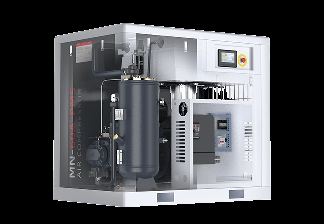
MINNUO offers a full range of both oil-lubricated screw air compressors and water-lubricated oil-free screw compressors, so the right answer for your floor depends on your machine mix — not on a one-size-fits-all sales pitch. When in doubt, run a differential cost analysis: the price premium of oil-free is real, but so is the cost of one contaminated spindle or one rejected tool-change cycle on a precision part.
IV. Step 3 — Pressure, Quality, and the Air-Treatment Train
Set the system pressure from the highest-pressure consumer on your floor, not from the compressor’s maximum. For most CNC shops that is 100 psi at the machine, which means a compressor discharge setting of roughly 110–125 psi once you account for the pressure drop through dryers, filters, and piping. Do not run the whole plant at 120 psi because one old machine “likes” 110 — instead, regulate down at the point of use, because pressure you do not use is energy you pay for.
The Minimum Air-Treatment Train
| Stage | Purpose | Selection note |
|---|---|---|
| Refrigerated dryer | Remove bulk moisture to a 38°F (3°C) pressure dew point | Standard for CNC shops; enough for most climates |
| Coalescing filter (0.3–1 µm) | Remove oil aerosol and fine particles | Essential for oil-injected systems feeding machine FRLs |
| Particulate/desiccant (optional) | Ultra-dry air for precision spindles | Only if your machines’ spec demands a lower dew point |
| Point-of-use regulator + FRL | Set exact pressure at each machine | A machine-specific FRL at every spindle is not optional |
One rule of thumb worth repeating: if you see water droplets when you open a drain valve at a machine, your dryer is undersized or your maintenance interval is wrong. Water in a CNC spindle taper is not a nuisance — it is a corrosion and repeatability failure waiting for a rainy season.
V. Step 4 — Storage, Piping, and Layout
Compressed air storage is what saves you from buying a compressor 40% bigger than you need. Because CNC machines demand sharp bursts, a properly sized receiver tank lets the compressor run steadily while the tank absorbs the peaks. As a starting point, size the receiver at 1–1.5 gallons per CFM of compressor output — a 30 CFM compressor wants at least 30–45 gallons of storage.
Piping Rules for CNC Floors
- Use a ring main or a properly sized header, not a single dead-end branch feeding a row of machines — a dead-end line gives the last machine both the lowest pressure and the wettest air.
- Slope the main toward drain points and install drip legs with drains at every low point and every drop to a machine.
- Take machine drops from the top of the header, not the bottom, so condensed water and debris stay in the main and never fall into the machine FRL.
- Size header pipe for velocity, not just pressure drop — keep line velocity below about 20 ft/s to limit pressure drop and water carry-over.
On a floor with older and newer equipment — including second-hand doosan machine tools — do not assume the machines you buy used have the same air connection or internal filtration as your existing fleet. A used machine from a marketplace may arrive with a different FRL specification, a different coupling, or no FRL at all; budget a machine-specific point-of-use package for every used unit you bring in. This is one of the cheapest “hidden costs” of buying used machinery that most buyers discover only after the first shift.
VI. Step 5 — CNC-Specific Air Management
Beyond the hardware, three operational practices make the difference between a system that works and a system that survives.
1. Put a Dedicated FRL on Every Machine
Do not share one filter-regulator-lubricator across two machines. Each machine’s FRL should be set to that machine’s spec, and the lubricator should be filled with the machine manufacturer’s recommended oil. Over-lubrication is as harmful as under-lubrication: excess oil aerosol travels downstream into the very valves and spindles it is meant to protect.
2. Check the Dew Point, Not Just the Pressure
Pressure tells you the machine can move; dew point tells you the air will not corrode the machine. If your plant runs a refrigerated dryer, verify the pressure dew point at the machine (not just at the dryer outlet) with a portable dew-point meter at least quarterly, and after any piping change.
3. Standardize the Pressure Map
Document the required pressure at every machine and post it at the machine. When a machinist turns up the regulator “because the chuck is slipping,” the real fix is usually not more pressure — it is a worn regulator seat, a leaking cylinder seal, or a clogged filter. Turning up the pressure masks the fault, wastes energy, and can damage pneumatic components rated for a lower maximum.
VII. Maintenance Discipline for the Whole System
A CNC air system fails slowly, and the failures are usually misdiagnosed as machine faults. Build these checks into your preventive maintenance schedule:
| Frequency | Check | What it prevents |
|---|---|---|
| Daily | Drain receiver tank and drip legs | Water in machine air lines |
| Weekly | Inspect FRLs for oil level, water, filter saturation | Valve and spindle contamination |
| Weekly | Walk the line listening for hissing leaks | Air loss and pressure droop (10–20% of output is typical) |
| Monthly | Record compressor run hours, load/unload cycles | Sizing errors and valve wear |
| Quarterly | Verify pressure dew point at machines | Corrosion and condensation failures |
| Annually | Re-torque piping joints, replace filter elements and separator | Sudden pressure loss and oil carry-over |
If your shop recently added a used machining center, treat its air connection as a new-commissioning task: run the machine through a full tool-change and spindle-purge cycle on manual and watch the pressure gauge during the event. If the needle drops by more than a few psi, your system is undersized or your piping is choked, and you will fight intermittent alarms until you fix it. This commissioning step alone prevents most of the “the used machine is broken” service calls that are actually air-system problems.
VIII. Common Symptoms and Their True Root Causes
Most shop-floor air problems present as machine symptoms. Here is the quick diagnostic map:
| Symptom | Likely root cause (check in this order) |
|---|---|
| Intermittent “low air pressure” alarm during tool change | Peak demand exceeds supply; receiver too small; FRL undersized |
| Tool changer stops mid-cycle | Pressure droop under simultaneous demand; sticky solenoid from moisture |
| Spindle taper contamination / poor repeatability | Wet or oily air; missing or saturated coalescing filter |
| Random pneumatic valve failure | Water carry-over; over-lubrication; wrong lubricant oil |
| Premature compressor load/unload cycling | Receiver too small; leaking blow-off valves; air leaks |
| Machine runs fine in winter, alarms in summer | Refrigerated dryer undersized for warm-weather dew point |
IX. Why Undersized and Unmaintained Systems Cost You Parts Per Hour
It is worth stating the economics plainly. An undersized compressor does not just mean a louder machine — it means the pressure at the machine drops exactly when the machine needs it most (tool change, spindle purge, workholding clamp), which produces scrap, machine alarms, and worn pneumatic components. Multiply that across a two-shift operation and the cost of the correct compressor is paid for in avoided scrap and downtime within months. For shops operating used machinery, the pressure economics are the same, with one additional risk: a used machine’s air system components (valves, cylinders, FRLs) may already be worn, and they are more sensitive to water and oil contamination than new components. Clean, dry, stable air is the cheapest insurance you can buy for a used CNC asset.
X. Conclusion
A CNC machine shop’s compressed air system is not a utility — it is a production-critical utility, and it is treated as an afterthought at the shop’s peril. Size for peak, not average. Choose oil-free where your machines require it. Fit a proper dryer, filter, and point-of-use FRL package. Give the system enough storage and a correctly designed header. And maintain the discipline to drain, inspect, and dew-point-check on schedule. Whether your floor runs brand-new machining centers or a fleet of used machinery including second-hand doosan machine tools, the air system is the one shared component you cannot afford to underspecify — because when the air fails, every machine on the line fails with it.
If you are planning a new air system or a shop expansion, the MINNUO engineering team can help you size the compressor, dryer, and storage to match your exact machine mix. Contact our sales and technical team with your machine list and we will send you a free compressor sizing proposal.
FAQ
Q1: What pressure should I run for a CNC machining center?
Run 100 psi at the machine as the standard for tool changing, spindle purge, and workholding. Set the compressor discharge 10–25 psi higher to cover the pressure drop through the dryer, filters, and piping, and regulate down at each machine’s FRL.
Q2: Do I need an oil-free compressor for a CNC shop?
Only if your machines specify oil-free air, or if you run precision spindles and through-spindle applications where any oil carry-over is unacceptable. For standard blow-off and tool-changing duty, an oil-injected screw compressor with proper coalescing filtration is usually sufficient.
Q3: Why does my machine alarm “low air pressure” even though the compressor gauge looks fine?
Almost always because the compressor gauge reads the header, not the machine. Under peak demand (tool change), pressure at the machine drops far below header pressure due to undersized piping, an undersized receiver, or a worn FRL. Measure the pressure at the machine during the event.
Q4: Can I buy a used machining center and just plug it into my existing air line?
You can, but you should not. Verify the machine’s air consumption and FRL specification from its manual, budget a point-of-use filter-regulator package for the machine, and commission it with a full tool-change cycle while watching the pressure gauge. Most “used machine air failures” are existing-line problems, not machine problems.
Q5: How do I know if my air dryer is too small?
If you open a drain at the machine and see water, or if the machine’s pressure dew point at the machine is above about 50°F (10°C) in summer, the dryer is undersized or its maintenance interval is wrong. Measure dew point at the machine, not just at the dryer outlet.
Q6: Is a larger receiver tank a substitute for a bigger compressor?
Partly. A correctly sized receiver absorbs the peak bursts of a CNC floor and can let a smaller compressor run more steadily. But it does not create air — if average demand already exceeds supply, no tank size will fix it. Size the tank at roughly 1–1.5 gallons per CFM of compressor output, and size the compressor for average-plus-margin with the tank covering the peaks.