Screw compressors vibrate. In normal operation, the meshing rotors, rolling element bearings, timing gears, and fluid flow all produce vibration signatures that are consistent and predictable. When a bearing begins to spall or a gear tooth develops a fatigue crack, those signatures change. Vibration analysis detects these changes months before the deteriorating component fails outright—often before any audible noise, temperature rise, or performance degradation alerts operators that something is wrong. For maintenance teams managing critical compressed air or process gas systems, vibration analysis is the most powerful predictive tool available.
I. What Vibration Analysis Measures
Every machine fault produces a characteristic vibration pattern. Understanding what is being measured and what it reveals is the foundation of effective vibration analysis.
Vibration is oscillatory motion around a reference position. In screw compressors, this motion is measured at bearing housings and other accessible locations where the forces generated by internal components transmit to the machine surface. The measurement captures three parameters: amplitude, frequency, and phase.
Amplitude describes how much the machine surface moves—typically measured as acceleration, velocity, or displacement. Velocity is the most commonly used parameter for general-purpose machinery assessment because it weights mid-frequency faults effectively. Acceleration captures high-frequency phenomena such as bearing component resonances and early-stage gear mesh problems. Displacement is useful for very low frequency, high-amplitude motion such as imbalance and misalignment.
Frequency identifies the source of the vibration. Each rotating component generates vibration at specific frequencies related to its rotational speed and geometry. The compressor’s male rotor turning at 3,000 RPM produces vibration at 50 Hz. A bearing with a damaged inner race produces vibration at a frequency determined by the bearing geometry and the shaft speed passing over the defect. By matching measured frequencies to the calculated fault frequencies of each component, the analyst identifies which component is generating abnormal vibration.
Phase measures the timing relationship between vibration signals from different locations or between vibration and a reference such as shaft rotation. It distinguishes between faults that produce similar frequency patterns but have different physical causes—for example, imbalance versus misalignment.
II. Bearing Fault Detection
Bearings are the most common source of vibration-detected faults in screw compressors. Rolling element bearings support radial and axial loads on both rotor shafts, and their condition determines whether the rotors maintain the precise clearances required for efficient compression.
Each bearing generates four characteristic defect frequencies that correspond to damage on specific components. The inner race defect frequency occurs when a fault on the rotating inner ring contacts each rolling element per revolution. The outer race defect frequency is produced by fixed outer ring damage. The rolling element spin frequency indicates damage to the balls or rollers themselves. The cage frequency, typically the lowest of the four, corresponds to the rotational speed of the cage assembly and can indicate cage wear or lubrication problems.
These frequencies are calculated from the bearing geometry and the shaft rotational speed. Most vibration analysis software calculates them automatically when bearing part numbers are entered. A vibration spectrum showing elevated amplitude at one of these frequencies, or at harmonics of it, strongly indicates bearing damage at the corresponding location.
Bearing faults progress through predictable stages that vibration analysis can track. The earliest indication is often high-frequency energy in the acceleration spectrum, appearing at 30 kHz to 50 kHz—frequencies too high for human hearing and invisible on standard velocity spectra. As the defect grows, it excites bearing component natural frequencies, producing resonant peaks that appear at lower frequencies. At this stage, the bearing is damaged but still functional. Further progression produces distinct peaks at the bearing defect frequencies, and eventually harmonics and sidebands appear as the damage spreads across the race surface. At the final stage, the bearing is producing high vibration across a broad frequency range, noise is often audible, and failure is imminent.
The transition from early-stage to end-stage can take months under normal operating conditions, providing ample time to plan a bearing replacement during scheduled downtime. This lead time is the primary value of vibration analysis: it allows maintenance to be planned rather than reactive.
III. Identifying Timing Gear and Mechanical Drive Problems
Timing gears maintain the precise synchronization between male and female rotors in oil-free screw compressors. In oil-flooded machines, timing gears are sometimes present as well, though the oil film between rotors provides the primary synchronization. Gear problems develop through several mechanisms, each producing a distinct vibration signature.
The fundamental gear mesh frequency equals the number of gear teeth multiplied by the shaft rotational speed. A 36-tooth gear on a shaft turning at 3,000 RPM produces gear mesh vibration at 1,800 Hz. Under normal conditions with proper lubrication and alignment, the amplitude at this frequency is low and stable. When gear mesh amplitude increases—either in absolute terms or relative to historical baselines—it indicates deteriorating gear condition.
Gear wear produces elevated amplitude at the gear mesh frequency and its harmonics, with sidebands appearing at the rotating speed of the gear carrying the fault. These sidebands arise because a worn or damaged tooth modulates the mesh vibration once per revolution. The spacing of the sidebands identifies which gear has the problem.
Tooth loading problems, often from misalignment between the gear shafts, produce gear mesh amplitude that varies with load. If vibration increases when the compressor loads and decreases when it unloads, gear alignment is suspect.
Gear tooth cracking or spalling produces sharp transient impacts each time the damaged tooth enters mesh. These impacts appear in the time waveform as periodic spikes at the rotating frequency of the gear carrying the damage. The corresponding spectrum shows elevated noise floor across a wide frequency range rather than neat, narrow peaks.
Coupling problems transmit vibration between the motor and compressor. Misalignment produces vibration at twice the shaft rotational frequency, often with a pronounced axial component. Worn or loose couplings produce harmonics of rotating speed and may generate impacting visible in the time waveform.
IV. Distinguishing Between Vibration Sources
A screw compressor’s vibration signature is a composite of multiple sources operating simultaneously. Separating them requires systematic analysis.
Rotational speed vibration—one times the shaft speed—usually originates from rotor imbalance. An unbalanced rotor produces vibration proportional to the imbalance mass and the square of the rotational speed. This vibration is predominantly radial and increases predictably with speed. If vibration at rotational speed changes over time, it may indicate deposit buildup on the rotors, uneven wear, or a balance weight that has shifted.
Harmonics of rotational speed, particularly two times and three times running speed, suggest misalignment or looseness. Misalignment between the motor and compressor shafts produces a strong twice-running-speed component in the radial direction and often a significant axial component. Structural looseness or inadequate foundation stiffness produces multiple harmonics of running speed, often with erratic amplitude behavior.
Fluid-related vibration originates from the air or gas flow through the compressor. The pocket passing frequency—the rate at which rotor lobes pass the discharge port—is equivalent to the number of male rotor lobes multiplied by the male rotor speed. A four-lobe male rotor at 3,000 RPM produces a pocket passing frequency of 200 Hz. Elevated amplitude at this frequency or its harmonics can indicate flow instability, surge incipience, or discharge pulsation problems.
Electrical vibration from the drive motor appears at frequencies related to line frequency and motor construction. An induction motor produces vibration at twice line frequency—120 Hz for a 60 Hz supply—due to electromagnetic forces. This frequency disappears immediately when the motor is de-energized, distinguishing it from mechanical vibration. Broken rotor bars, eccentric air gaps, and stator problems produce additional characteristic patterns.
V. Setting Up an Effective Monitoring Program
A vibration monitoring program must balance thoroughness against practicality. Not every compressor justifies the same level of monitoring investment.
For critical compressors—those whose failure stops production—continuous online monitoring with permanently mounted accelerometers provides the earliest possible warning and captures transient events that periodic readings miss. The investment in sensors, cabling, and monitoring hardware typically returns value through a single avoided failure.
For important but non-critical machines, periodic route-based monitoring using a portable data collector and analyzer is the standard approach. Measurements are taken at defined locations on a schedule—monthly or quarterly, depending on the machine’s criticality and failure history. The same locations, sensor mounting method, and machine operating conditions should be used each time to ensure trendability.
For small or non-critical compressors, simple vibration severity checks with a handheld meter may be sufficient. An overall velocity measurement compared to ISO 10816-3 or similar standard provides a rough indication of machine condition. This approach will not identify developing bearing defects at an early stage, but it flags machines that require more detailed investigation.
Measurement locations should be standardized and documented. On screw compressors, typical measurement points include the drive-end and non-drive-end bearing housings on both the male and female rotor shafts, the motor bearings, and the gearbox or coupling housing. Triaxial measurements—recording vibration in vertical, horizontal, and axial directions at each location—provide the most complete picture.
Baseline measurements taken when the compressor is in known good condition—ideally immediately after commissioning or a major overhaul—establish the reference against which all future measurements are compared. Without a baseline, trending is impossible, and the ability to detect gradual deterioration is severely limited.
VI. Using Vibration Data for Maintenance Decisions
Vibration data supports maintenance decision-making by providing objective evidence of machine condition and the rate at which that condition is changing.
A bearing showing elevated vibration at an early-stage fault frequency can safely continue in operation, with monitoring frequency increased to track progression. The maintenance team has months to plan the replacement, order parts, and schedule the work during a convenient window. This is the ideal outcome of vibration analysis.
A bearing showing rapidly increasing vibration amplitude across multiple fault frequencies, with harmonics and sidebands appearing, requires prompt attention. The replacement should be scheduled at the next available opportunity, and operation should be closely monitored in the interim.
A bearing in the final stages of degradation—producing high vibration across a broad frequency range with audible noise—requires immediate shutdown. Continuing to operate under these conditions risks catastrophic failure that can damage other components, turn a bearing replacement into an airend replacement, and extend downtime from hours to weeks.
The vibration analyst does not make the final maintenance decision. The analyst provides data, interpretation, and a recommended course of action. The maintenance manager integrates this information with production schedules, parts availability, and other priorities to determine when and how to act. Clear communication between analyst and decision-maker is essential.
FAQ
Q1: How often should vibration measurements be taken on a screw compressor?
Critical machines justify monthly measurements with continuous online monitoring of key points. Standard process compressors can be monitored quarterly. Less critical machines may be measured semi-annually. The interval should be shortened if a fault is detected and the machine is being monitored through its progression to failure.
Q2: Can vibration analysis detect problems with the airend itself?
Yes. Changes in the pocket passing frequency amplitude can indicate rotor clearance changes, deposit buildup, or developing rotor contact. The airend’s vibration signature is complex because it includes contributions from both rotors, their bearings, and the fluid flow. A experienced analyst can distinguish normal variation from developing problems.
Q3: What is the difference between overall vibration and spectrum analysis?
Overall vibration is a single number—typically velocity in millimeters per second or inches per second—that summarizes the total vibration energy across a broad frequency range. It provides a quick health check but does not identify the source of elevated vibration. Spectrum analysis breaks down the vibration into its frequency components, allowing identification of which component is generating which vibration. Overall readings can flag a problem. Spectrum analysis identifies it.
Q4: Do variable speed compressors complicate vibration analysis?
Yes. Because fault frequencies change with speed, the vibration signature shifts. Measurements should be taken at a consistent speed and load condition for trendability. Many vibration analyzers can calculate fault frequencies from a speed reference and automatically adjust their analysis, but trending across different speeds requires careful data handling.
Q5: Can I do vibration analysis myself, or do I need a specialist?
A handheld vibration meter for overall readings requires minimal training. Route-based data collection with a portable analyzer requires training in measurement technique and basic interpretation. Detailed spectrum analysis and fault diagnosis requires experience that develops over years. Many facilities own their data collectors and contract specialist analysts to interpret the data and provide recommendations.
Q6: What other predictive technologies complement vibration analysis?
Oil analysis and vibration analysis are strongly complementary. Vibration detects mechanical deterioration. Oil analysis detects wear through the particles shed into the lubricant, often before vibration levels change. Together, they provide earlier and more definite fault detection than either technology alone. Thermography provides supplemental information, particularly for detecting lubrication system problems and coupling misalignment.
Conclusion
Vibration analysis transforms maintenance from reactive to planned. It detects bearing defects, gear damage, and rotor problems months before they become audible or visible, providing the lead time needed to order parts, schedule downtime, and avoid production interruptions. The technology distinguishes between fault types and severities, guiding maintenance resources to the machines that need them most and preventing unnecessary intervention on machines that are operating normally.
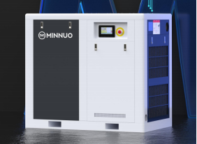
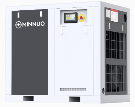
At MINNUO, our screw compressors are commissioned with baseline vibration measurements that establish the reference for future condition monitoring. We provide vibration measurement locations, recommended monitoring frequencies, and machine-specific fault frequency data to support your condition monitoring program. For existing installations, our service team offers vibration surveys, baseline establishment, and diagnostic analysis to identify developing problems and recommend appropriate corrective actions. Whether you are building a new condition monitoring program or troubleshooting unusual vibration in an existing compressor, MINNUO provides the technical support to protect your compressed air investment through predictive maintenance.

 Email
Email sales:+86 15312799623