Hydrogen is fourteen times lighter than air. A leak that would pool methane at floor level sends hydrogen jetting upward at nearly 20 meters per second—straight toward the ceiling, where it accumulates in pockets that can reach flammable concentrations within minutes. Ventilation is not an accessory to hydrogen compressor safety; it is the primary engineered safeguard that prevents a minor leak from becoming an explosive hazard. Proper ventilation design dilutes and removes hydrogen before concentrations approach the 4% lower flammable limit. This guide provides the engineering requirements for hydrogen compressor ventilation systems.
I. Why Hydrogen Demands Different Ventilation Design
Hydrogen’s physical properties fundamentally change ventilation requirements compared to heavier-than-air gases.
1. Buoyancy-Driven Flow
Hydrogen’s density at standard conditions is 0.0838 kg/m³ —approximately 1/14 the density of air (1.2 kg/m³). A hydrogen leak immediately accelerates upward due to buoyancy forces. This rapid vertical movement creates a plume that entrains surrounding air, naturally diluting the hydrogen as it rises.
Design implication: Ventilation exhaust must be located at the highest point of the enclosure or room. Low-level exhaust, standard for heavier-than-air gases, is ineffective for hydrogen.
2. Diffusion Velocity
Hydrogen diffuses through air at 0.61 cm²/s —four times faster than methane and twelve times faster than gasoline vapor. While this rapid diffusion aids dilution, it also means hydrogen spreads quickly throughout an enclosure, finding and accumulating in any high-point dead zone.
Design implication: Enclosure geometry must eliminate stagnant high-point pockets. Sloped ceilings or multiple high-point exhausts prevent accumulation.
3. Concentration Stratification
Unlike heavier gases that form layers near the floor, hydrogen forms concentration gradients from ceiling downward. Even with ventilation, the highest hydrogen concentration always occurs at the highest elevation.
Design implication: Gas detection sensors and ventilation exhaust must be positioned at the enclosure ceiling, not mid-wall or floor level.
II. Natural vs. Mechanical Ventilation
The choice between natural and mechanical ventilation depends on enclosure configuration and leak scenarios.
1. Natural Ventilation
Natural ventilation relies on buoyancy forces and wind to move air through an enclosure without fans or blowers.
Requirements per NFPA 2 and ISO 19880:
- Open area: Minimum 25% of total wall area open to outside atmosphere
- High-level opening: Ventilation openings at or near ceiling level on all walls
- Low-level inlet: Unobstructed air inlets at floor level
- No dead zones: Ceiling configuration must not create stagnant pockets
Applicability:
- Outdoor installations with weather-protective canopies
- Open-sided compressor shelters
- Mild climates where full enclosure is unnecessary
Limitations:
- Cannot achieve the reliability of mechanical systems
- Wind-dependent; calm conditions reduce effectiveness
- Not suitable for occupied buildings or enclosed compressor rooms
2. Mechanical Ventilation
Mechanical ventilation uses powered fans to guarantee airflow regardless of ambient conditions.
Requirements per NFPA 2:
- Continuous operation while hydrogen is present in the system
- Minimum ventilation rate: Per calculation (see Section III)
- Emergency override: Capability to increase to maximum airflow on gas detection
- Power supply: Connected to emergency or uninterruptible power where critical
3. Selection Criteria
| Condition | Recommendation |
| Outdoor installation, open structure | Natural ventilation acceptable |
| Indoor compressor room | Mechanical ventilation required |
| Below-grade or enclosed space | Mechanical ventilation required |
| Occupied building | Mechanical ventilation required |
| High-leak-potential equipment | Mechanical ventilation strongly recommended |
III. Ventilation Rate Calculations
Ventilation rate must be calculated based on credible leak scenarios, not arbitrary air change rates.
1. Leak Rate Basis
Method A: Percentage of system inventory
Assume a credible leak of 0.5-1.0% of maximum system flow capacity per minute.
For a compressor handling 500 Nm³/hr hydrogen:
- Leak rate = 500 × 0.01 = 5 Nm³/hr = 0.083 Nm³/min hydrogen
Method B: Specific leak area
Assume a leak equivalent to a defined orifice size per equipment type:
- Compressor shaft seal: 0.25 mm equivalent diameter
- Flange connection: 0.1 mm equivalent diameter
- Valve packing: 0.05 mm equivalent diameter per valve
Method C: Manufacturer data
Use manufacturer-specified leakage rates for specific equipment when available.
2. Dilution Ventilation Calculation
The dilution equation determines ventilation airflow required to maintain hydrogen below a target fraction of LFL:
Q = (Qₕ₂ × 100) / (C_target × LFL × SF)
Where:
- Q = Required ventilation airflow (m³/min)
- Qₕ₂ = Hydrogen leak rate (m³/min)
- C_target = Target hydrogen concentration (% LFL)
- LFL = 4% (hydrogen lower flammable limit as decimal, 0.04)
- SF = Safety factor (typically 2-4)
3. Worked Example
A compressor enclosure with estimated leak rate of 0.083 Nm³/min H₂. Target concentration 25% LFL with safety factor 4:
Q = (0.083 × 100) / (25 × 0.04 × 4) = 8.3 / 4 = 2.08 m³/min (73 CFM)
4. Air Change Rate Check
Convert calculated airflow to air changes per hour and verify minimum:
ACH = (Q × 60) / V_enclosure
For a 30 m³ enclosure: ACH = (2.08 × 60) / 30 = 4.2 air changes per hour
NFPA 2 typically specifies a minimum of 12 air changes per hour for indoor hydrogen equipment rooms regardless of calculated requirement. Where calculation yields lower values, the standard minimum applies.
Recalculated airflow for 12 ACH: Q = (12 × 30) / 60 = 6.0 m³/min (212 CFM)
IV. Impact of Ventilation on Hazardous Area Classification
Ventilation effectiveness directly determines the extent of hazardous zones per IEC 60079-10-1.
1. Ventilation Availability Categories
| Availability | Definition | Example |
| Good | Continuous, reliable ventilation | Redundant mechanical fans with backup power |
| Fair | Normally present, occasional interruptions | Single mechanical fan without backup |
| Poor | Unreliable or intermittent | Natural ventilation subject to weather |
2. Impact on Zone Classification
Superior ventilation reduces the extent and severity of hazardous zones:
| Ventilation + Leak Scenario | Typical Zone | Extent |
| High ventilation, small leak | Zone 2 or non-hazardous | Very limited |
| Medium ventilation, medium leak | Zone 2 around equipment | 1-3 meters from source |
| Low ventilation, any leak | Zone 1 or Zone 2 | Extended, entire enclosure may classify |
| Failed ventilation, leak | Zone 1 or Zone 0 | Entire enclosure |
3. Ventilation Assessment Documentation
Hazardous area classification must document:
- Ventilation type (natural or mechanical)
- Ventilation availability (good, fair, poor)
- Calculated or measured dilution capacity
- Gas detection and ventilation interlocks
- Sensitivity of zone classification to ventilation failure

V. Ventilation System Design Features
Effective hydrogen ventilation requires specific design elements.
1. Intake Location
- Low elevation: Floor level or near-grade to introduce dense, cool air
- Clean air source: Away from potential hydrogen vent discharges or other contaminants
- Protected from weather: Louvers with rain protection that do not restrict airflow
- Multiple inlets: Distributed around enclosure perimeter for uniform airflow
2. Exhaust Location
- Highest point: At ceiling peak or enclosure top
- Multiple exhausts: For large enclosures, multiple ceiling-level exhausts prevent dead zones
- Vent stack: Exhaust ducted to safe outdoor location, not into adjacent spaces
- Discharge height: Minimum 3 meters above roofline or per local code
3. Airflow Path Design
The ideal airflow path sweeps hydrogen from equipment toward ceiling exhaust without creating stagnant zones:
| Design Feature | Purpose |
| Inlet at floor, exhaust at ceiling | Utilizes hydrogen buoyancy |
| Airflow from clean to potentially contaminated areas | Protects personnel and non-classified areas |
| No horizontal barriers | Prevents stratification pockets |
| Sloped ceiling to exhaust | Eliminates flat-ceiling dead zones |
4. Ducting Considerations
- Non-combustible construction (steel, aluminum)
- Bonded and grounded to prevent static accumulation
- Slope upward toward exhaust (hydrogen follows slope)
- Cleanout access for inspection
- No fire dampers that could close and trap hydrogen
VI. Fan and Electrical Requirements
Ventilation fans in hydrogen service must meet explosion protection requirements.
1. Fan Motor Classification
| Installation Location | Fan Motor Requirement |
| Within classified zone | ATEX/IECEx certified for applicable zone |
| Outside classified zone, handling hydrogen-air mixture | ATEX/IECEx certified (Zone 1 or 2 per assessment) |
| Outside classified zone, fresh air only | Standard motor acceptable |
2. Fan Construction Materials
- Impeller and housing: Aluminum, brass, or stainless steel (non-sparking materials)
- Inlet cone: Non-ferrous metal to prevent rubbing sparks
- Shaft seal: Gas-tight to prevent leakage into motor compartment
- Bearings: Anti-static belting and properly grounded
3. Fan Configuration Options
| Configuration | Advantage | Disadvantage |
| Roof-mounted axial | Direct upward discharge | Exposed to weather |
| Wall-mounted centrifugal | Protected installation | Requires more space |
| Inline duct fan | Remote motor location | Pressure drop through ductwork |
4. Electrical Supply and Backup
- Normal power: Primary ventilation on facility power
- Emergency backup: If hydrogen supply cannot be isolated on power failure, ventilation must have backup power (generator or UPS)
- Interlock: Ventilation failure initiates automatic hydrogen isolation
VII. Gas Detection and Ventilation Interlocks
Ventilation and gas detection work as an integrated safety system.
1. Normal Operation
Continuous ventilation at calculated base rate maintains safe conditions during normal compressor operation.
2. Low-Level Detection Response
| Detection Level | Ventilation Response |
| 10-20% LFL | Increase ventilation to maximum |
| 25-40% LFL | Compressor shutdown, ventilation maximum |
| 50%+ LFL | Emergency shutdown, facility evacuation |
3. Ventilation Failure Response
Loss of ventilation is an abnormal condition requiring:
- Immediate alarm to operator or control room
- Automatic compressor shutdown if ventilation not restored within predetermined time
- Hydrogen supply isolation if compressor shutdown is not sufficient
- Prohibition of compressor restart until ventilation restored and hydrogen concentration verified safe
4. Start-Up Permissive Logic
Compressor start must be inhibited unless:
- Ventilation system is running and airflow verified (differential pressure switch or flow sensor)
- Hydrogen detection system is operational with no alarms
- Minimum purge time after ventilation start completed
VIII. Outdoor and Semi-Enclosed Installations
Not all hydrogen compressors are installed indoors. Outdoor and semi-enclosed installations have specific ventilation design considerations.
1. Fully Outdoor (No Enclosure)
- Advantage: Unlimited natural ventilation; no accumulation possible
- Considerations:
- Instrumentation and controls require weather protection
- Maintenance access during inclement weather
- Local regulations may still require gas detection monitoring
2. Canopy or Weather Shelter
- Must be open-sided on minimum two opposing walls
- Ceiling must be sloped or peaked to roof vents
- No flat ceiling that could trap hydrogen
- Minimum opening area: 25% of each wall area (NFPA 2 guidance)
3. Semi-Enclosed Compressor Packages
Manufacturer-packaged compressor enclosures must include:
- Built-in ventilation fan(s) with airflow verification
- Integrated hydrogen detection
- Ventilation failure alarm wired to compressor control system
- Access doors interlocked or procedure-controlled
IX. Testing and Maintenance of Ventilation Systems
Ventilation system effectiveness degrades without routine maintenance.
1. Commissioning Testing
- Smoke test: Verify airflow paths sweep all areas of enclosure
- Flow measurement: Confirm design airflow at each exhaust point
- Gas trace test: Introduce helium or hydrogen trace to verify detection and ventilation response
- Interlock verification: Test all ventilation-related shutdown functions
2. Routine Maintenance
| Task | Frequency |
| Fan belt tension and condition | Monthly |
| Airflow measurement at exhaust | Quarterly |
| Inlet louver cleanliness | Monthly |
| Fan motor current check | Quarterly |
| Differential pressure switch calibration | Annually |
| Full ventilation fail test | Annually |
3. Documentation
Maintain records of:
- Commissioning test results
- Routine airflow measurements
- Maintenance and calibration records
- Ventilation system modifications
FAQ
Q1: Is ventilation still required for an outdoor hydrogen compressor?
A1: For truly outdoor installations with no enclosure, natural ventilation is typically sufficient and no mechanical ventilation is required. However, if the compressor includes a factory enclosure or weather canopy, even outdoors, enclosure ventilation is required to prevent hydrogen accumulation inside the enclosure.
Q2: Can HVAC systems be used for hydrogen ventilation?
A2: Standard HVAC systems are not designed for explosive gas service. Modifications required include ATEX-certified fans and controls, elimination of recirculation (100% fresh air, 100% exhaust), and integration with gas detection. Purpose-designed ventilation systems are generally preferred.
Q3: What is the minimum ventilation rate per NFPA 2?
A3: NFPA 2 specifies a minimum of 1 CFM per square foot of floor area OR 12 air changes per hour for indoor hydrogen equipment rooms, whichever is greater. Higher rates apply if the dilution calculation warrants them.
Q4: How do I ventilate a below-grade hydrogen compressor installation?
A4: Below-grade installations are problematic for hydrogen because it naturally rises. They require:
- Mechanical ventilation with exhaust from the highest ceiling point
- Ducted exhaust rising to an above-grade discharge point
- Redundant fans with backup power
- Continuous hydrogen monitoring with automatic isolation on ventilation failure
Many standards discourage below-grade hydrogen equipment installation.
Q5: Do I need to heat makeup air in cold climates?
A5: If the compressor requires a minimum operating temperature, makeup air heating may be necessary. However, heating coils must be rated for the electrical classification if located in a classified area, or located in a non-classified intake plenum.
Q6: What records do inspectors require for ventilation compliance?
A6: Typical inspector requests include ventilation calculation documentation, hazardous area classification drawing, fan certification, ventilation interlock test records, airflow measurement records, and gas detection calibration records.
Conclusion
Hydrogen compressor ventilation is an engineered safety system requiring specific design features distinct from general industrial ventilation. Exhaust must be located at the highest point, airflow must sweep all potential accumulation zones, and ventilation rate must be calculated based on credible leak scenarios—not generic air change rules. The interaction between ventilation and hazardous area classification means superior ventilation directly reduces the extent and severity of classified zones, affecting equipment costs and operational complexity. Integrated gas detection, automatic response logic, and routine maintenance ensure the ventilation system performs its safety function throughout the compressor’s operating life.
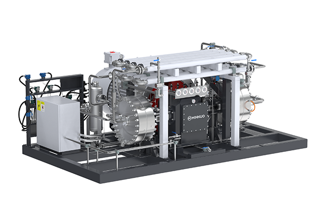
At MINNUO, our hydrogen compressors are supplied with comprehensive ventilation design support to ensure NFPA 2 and ISO 19880 compliance. Our engineering team performs ventilation rate calculations, assists with hazardous area classification, and specifies appropriate fan and control systems for your specific installation. Whether your compressor is installed indoors, outdoors, or within a packaged enclosure, MINNUO provides the documentation and technical support required for safe, compliant hydrogen compressor ventilation.
 Email
Email sales:+86 15952631531