Introduction
In a semiconductor fabrication facility (FAB), process gases must be delivered at precise pressures and purities. Silane, hydrogen, nitrogen trifluoride, and dozens of other specialty gases flow through miles of high-purity piping to tools where wafers are etched, deposited, and cleaned.
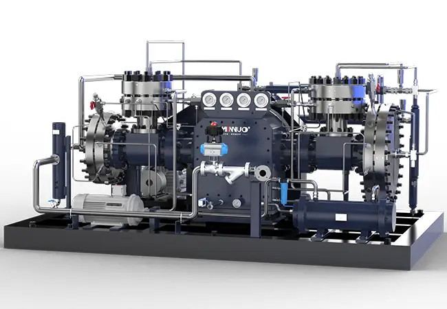
At the heart of many gas delivery systems is the diaphragm compressor. Unlike piston or rotary compressors, diaphragm designs seal the gas completely—no dynamic seals, no lubricants, no particles. For gases that are toxic, pyrophoric, or ultra-high purity, diaphragm compressors are the standard.
But sizing a diaphragm compressor for FAB service is not like sizing an industrial air compressor. Purity requirements, material compatibility, safety systems, and cleanroom integration all factor in.
This guide walks FAB engineers through the process of sizing a diaphragm compressor for semiconductor gas systems.
Understanding the Application: FAB Gas Systems
Before sizing, understand how the compressor fits into the larger system.
Gas delivery hierarchy
| Level | Component | Function |
| Bulk supply | Tube trailers, ISO containers | Gas delivered to facility |
| Gas cabinet | Cylinders or bulk storage | Primary supply point |
| Compressor | Diaphragm compressor | Boost pressure or transfer gas |
| Gas distribution | High-purity piping | Deliver to tools |
| Point of use | Pressure regulators, purifiers | Final conditioning |
Why compression is needed
- Pressure boost: Bulk gas arrives at low pressure (50-200 PSI) but tools need higher pressure (300-600 PSI)
- Cylinder evacuation: Recover residual gas from cylinders before disposal
- Gas transfer: Move gas from bulk storage to satellite locations
- Pressure maintenance: Maintain constant pressure during peak demand
FAB gas types requiring compression
| Gas | Properties | Compression Challenges |
| Silane (SiH₄) | Pyrophoric, toxic | Leak detection, inerting, materials |
| Hydrogen (H₂) | Flammable, embrittlement | Hydrogen embrittlement, sealing |
| Nitrogen trifluoride (NF₃) | Oxidizer, toxic | Material compatibility |
| Helium | Small molecule, high cost | Leakage, recovery |
| Specialty dopants (PH₃, AsH₃, B₂H₆) | Toxic, pyrophoric | Safety systems, containment |
Step 1: Determine Required Flow Rate
Flow rate is the starting point.
Measuring current usage
If replacing or supplementing an existing compressor:
- Log gas usage from tool manufacturers’ data
- Measure from existing system (flow meters, cylinder weights)
- Account for peak vs. average demand
Calculating for new tools
Tool manufacturers provide gas consumption data at rated operating conditions. Sum the requirements for all tools that will run simultaneously.
Peak vs. average
FAB gas demand is rarely steady. Multiple tools may purge simultaneously, creating peak demand. A buffer tank can smooth peaks, allowing a smaller compressor.
Example calculation
A deposition tool consumes 20 standard liters per minute (slpm) of silane. Peak during purge is 50 slpm for 30 seconds. With three tools, average consumption is 60 slpm, peak is 150 slpm.
A compressor sized for 60 slpm with a small buffer tank handles the 150 slpm peak.
Units conversion
Many FAB engineers work in slpm. For reference:
- 1 slpm = 0.0353 scfm
- 100 slpm = 3.53 scfm
Diaphragm compressors for FAB service are typically sized in slpm or scfm.
Step 2: Specify Inlet and Outlet Pressures
Pressure requirements vary by gas and application.
Common pressure ranges
| Application | Inlet Pressure | Outlet Pressure |
| Boosting from bulk | 50-200 PSI | 300-600 PSI |
| Cylinder evacuation | 10-50 PSI | 200-400 PSI |
| Gas transfer | 100-300 PSI | 300-600 PSI |
Compressor ratio
The ratio of outlet to inlet pressure (absolute) determines the number of stages required.
| Pressure Ratio | Stages Required |
| Up to 3:1 | Single stage |
| 3:1 to 8:1 | Two stage |
| 8:1 to 15:1 | Three stage |
| Above 15:1 | Four stage or more |
Example: Boosting hydrogen from 100 PSI to 500 PSI: ratio 5:1 → two stages.
Consider pressure drop
Account for pressure losses in piping, filters, and purifiers between the compressor and point of use. Oversize slightly.
Step 3: Define Purity and Material Requirements
In FAB applications, purity is paramount.
Target purity levels
| Application | Typical Purity Requirement |
| Bulk gas boosting | 99.999% (5N) to 99.9999% (6N) |
| Cylinder evacuation | 99.9-99.99% |
| High-purity gas transfer | 99.9999% (6N) or higher |
Contamination limits
For critical processes, contamination is measured in parts per billion (ppb) or parts per trillion (ppt). The compressor must not add:
- Particles (0.1 micron or larger)
- Metals (iron, chromium, nickel)
- Moisture
- Hydrocarbons
- Oxygen (for anaerobic gases)
Material selection
| Component | Material Requirements |
| Diaphragm | 316L stainless steel, Hastelloy, or Inconel |
| Head | Same as diaphragm (for compatibility) |
| Seals | PTFE, Kalrez, or metal seals |
| Wetted surfaces | Electropolished to 10-20 Ra microinch |
| Non-wetted | 304 or 316 stainless steel |
Surface finish
Electropolishing creates a smooth, passive surface that resists particle generation and corrosion. For ultra-high purity applications, specify electropolished wetted surfaces.
Step 4: Incorporate Safety and Redundancy
FAB gas systems require multiple layers of safety.
Leak detection
- Diaphragm rupture detection (space between diaphragm layers)
- Continuous gas monitoring in compressor enclosure
- Remote sensors in the FAB
Containment
- Secondary enclosure for toxic or pyrophoric gases
- Ventilation with exhaust to scrubber
- Positive pressure inerting for pyrophoric gases
Redundancy
For critical processes, consider:
| Configuration | Description | Best For |
| N+1 | One extra compressor | Most FABs |
| Dual 100% | Two complete systems | Continuous operation, no downtime |
| Automatic changeover | Backup starts on pressure drop | Critical tools |
Emergency systems
- Emergency shutdown (ESD) integration
- Backup power for safety systems
- Manual isolation valves
Sizing for redundancy
If specifying N+1, each compressor must be sized for the full load. With three compressors in N+1 (two operating, one standby), each is sized for 100% of demand.
Step 5: Account for FAB Environment
The compressor must be compatible with cleanroom conditions.
Location options
| Location | Pros | Cons |
| Sub-fab (below cleanroom) | No cleanroom contamination risk | Longer piping runs |
| Service corridor | Accessible, outside cleanroom | Space constraints |
| Gas cabinet area | Close to gas source | May be classified area |
Cleanroom integration
- If located in a cleanroom, the compressor must meet cleanliness standards
- Typically, compressors are placed in sub-fab or service corridors
- Gas is delivered through high-purity piping to the FAB
Classification requirements
For toxic or pyrophoric gases:
- Compressor may need to be in a gas cabinet or ventilated enclosure
- Electrical components must meet hazardous area classification
- Ventilation to scrubber may be required
Utility requirements
| Utility | Typical Requirement |
| Power | 208V or 480V three-phase |
| Cooling | Chilled water or air conditioning |
| Instrument air | Clean, dry compressed air (80-100 PSI) |
| Exhaust | Connection to facility exhaust |
| Nitrogen purge | For inerting and purging |
FAQ
Q1: What flow range do diaphragm compressors for FABs cover?
A1: Typical range is 1-500 slpm (0.04-18 scfm). Larger systems exist but are less common. For very high flows, multiple compressors may be used in parallel.
Q2: How many stages do I need for my pressure ratio?
A2: Up to 3:1 = single stage; 3-8:1 = two stage; 8-15:1 = three stage; above 15:1 = four stage. For most FAB applications (100 to 500 PSI), two stages suffice.
Q3: What is diaphragm rupture detection?
A3: A multi-layer diaphragm with a port between layers connected to a pressure sensor. If the gas-side diaphragm ruptures, gas enters the interlayer space and triggers an alarm before the second layer fails.
Q4: How often do diaphragms need replacement in FAB service?
A4: Typically every 4,000-8,000 hours, depending on gas, pressure, and cycle count. For critical processes, many FABs replace diaphragms on a preventive schedule (e.g., annually) regardless of condition.
Q5: Can I use the same compressor for different gases?
A5: Not recommended. Cross-contamination risk is too high. Each gas should have dedicated compressors, or compressors must be thoroughly cleaned and validated between gas changes.
Q6: What documentation do I need for a FAB diaphragm compressor?
A6: Typical requirements include: material certifications (wetted parts), surface finish measurements, cleanliness verification, helium leak test results, and factory acceptance test (FAT) records.
Q7: How long does a diaphragm compressor last in FAB service?
A7: With proper maintenance and clean gas, 10-15 years. The diaphragm itself is a consumable (2-3 years typical). Bearings, valves, and other components last much longer with regular service.
Conclusion
Sizing a diaphragm compressor for a FAB gas system is a specialized engineering task. It requires understanding not just flow and pressure, but also purity requirements, material compatibility, safety systems, and cleanroom integration.
Start with flow rate: average and peak. Determine inlet and outlet pressures; calculate the pressure ratio to find the number of stages needed. Define purity requirements to select materials and surface finishes. Incorporate safety and redundancy based on the gas’s hazards and the process’s criticality. And account for the FAB environment—sub-fab, service corridor, or cleanroom.
The right compressor delivers gas at the right pressure and purity, reliably, without contaminating the process. The wrong compressor can shut down a production line, ruin wafers, or create a safety incident.
For FAB engineers, the investment in proper sizing—and in quality equipment—pays back in uptime, yield, and peace of mind.
At MINNUO, we help semiconductor manufacturers size and select diaphragm compressors for FAB gas systems. From flow analysis to material selection to safety integration, we focus on solutions that deliver purity and reliability. Because in semiconductor manufacturing, the gas is as critical as the tool.
 Email
Email sales:+86 15366749631