Over the next decade, there will be a significant increase in fuel cell vehicles that rely on hydrogen as their power source. Commercial hydrogen refueling mother stations will play a critical role in providing hydrogen fuel for these vehicles. Therefore, ensuring the stability of hydrogen compressor operation is essential. This paper will conduct a case study of two diaphragm compressors at a mature hydrogen refueling station in Guangzhou, China, to determine what factors impact their long-term operation.
What is a diaphragm compressor?
The diaphragm compressor is a distinctive type of volumetric compressor that shares similar crankcase components with typical reciprocating compressors. However, it has a unique piston rod structure. The compressor operates using a hydraulic oil system. The diaphragm separates the working chamber into two different areas: the gas compression chamber and the hydraulic oil chamber. The diaphragm assembly completes the expansion, suction, compression, and exhaust process. This process occurs when the diaphragm receives hydraulic oil thrust.
Working principle of diaphragm compressors
As the piston moves from the cylinder side and stops towards the crankcase, the diaphragm reaches the balance position following the hydraulic oil. During this process, the gas chamber’s volume gradually increases, causing the residual gas to expand and reduce the gas chamber’s pressure. Once the gas chamber’s pressure falls below external force, the air intake process begins. Finally, as the piston reaches the crankcase side stop, the diaphragm reaches the stop position in the crankcase direction via the balance position, signifying the end of the air intake process.
Subsequently, as the piston moves in the opposite direction, it pushes the diaphragm to compress the gas using hydraulic oil, causing the gas chamber’s pressure to increase gradually. Once the gas chamber’s pressure reaches the exhaust pressure, the exhaust process begins. Finally, the diaphragm presses against the cylinder head’s dome surface again, signifying the end of the exhaust process and the completion of a working cycle in the diaphragm chamber.
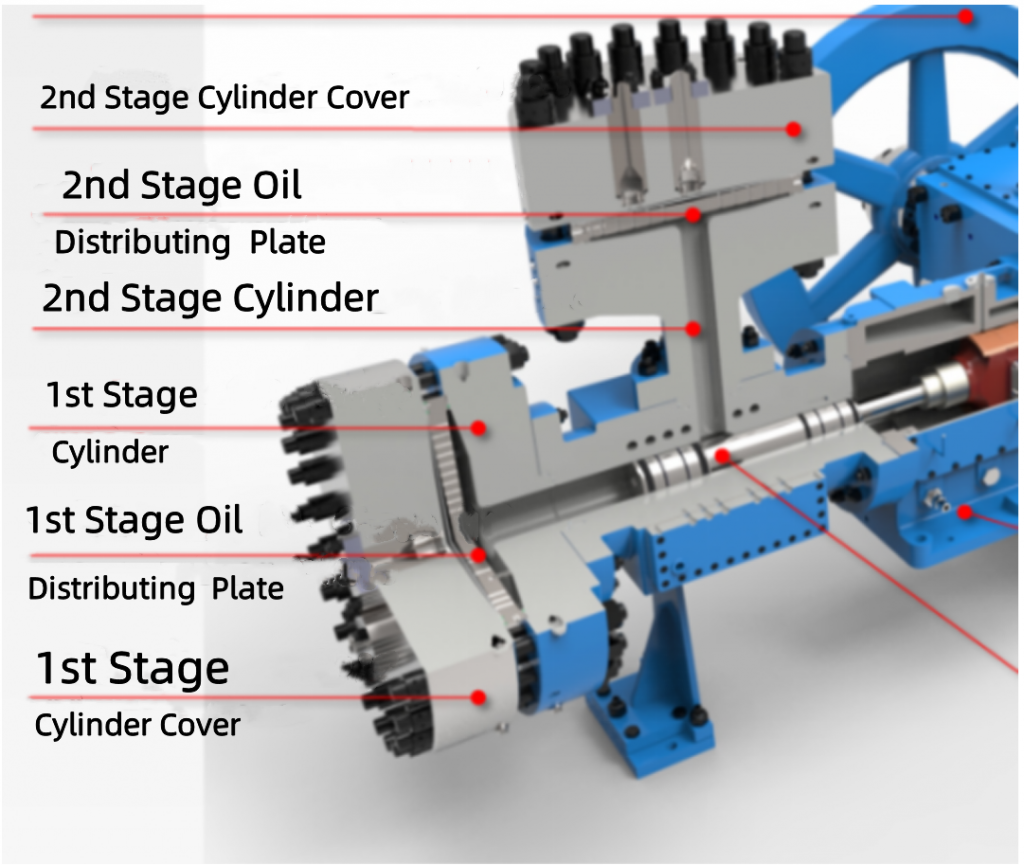
The parameters of the diaphragm compressor in use are shown in Table 1, and the internal structure is shown in Figure 1.
| Name | Capacity(Nm³/h) | Inlet pressure/MPa | Outlet pressure/MPa | Power/kW | Speed(r/min) |
| Machine 1 | 1300 | 2.9 | 22 | 220 | 372 |
| Machine 2 | 800 | 2.9 | 22 | 110 | 365 |
Diaphragm compressor failure factors
Since their launch on December 15, 2020, the maintenance records of machine 1 and machine 2 are listed in Table 2. Analysis of the failure situation indicates that O-ring seal failure and diaphragm rupture damage are the primary factors that impact the unit’s stable long-cycle operation.
| Name | Reason for inspection | Inspection content | Inspection time |
| Machine 1 | Seal leakage | Replace the follower valve O-ring | 2020.12.21 |
| Machine 1 | Diaphragm rupture | Replace right secondary diaphragm | 2021.2.7 |
| Machine 1 | Seal leakage | Replace the right primary diaphragm O-ring | 2021.3.29 |
| Machine 1 | Diaphragm rupture | Replace the right primary diaphragm | 2022.1.13 |
| Machine 1 | Seal leakage | Replace left one and two, right one and two diaphragm O-rings | 2022.2.15 |
| Machine 2 | Ruptured diaphragms and leaking seals | Replace secondary diaphragm and O-ring | 2021.7.15 |
| Machine 2 | Seal leakage | Replace secondary O-ring | 2022.1.29 |
Factors that damage O-ring seals
The reliability of the diaphragm compressor’s long-cycle operation depends on the life of the O-ring seal. A dependable O-ring seal can effectively decrease equipment inspection and maintenance costs while ensuring a high device start-up rate. The primary factors impacting the O-ring seal’s life in the diaphragm compressor include material selection, compression deformation, gap bite, distortion due to improper installation, temperature, and wear and tear.
Seal processing accuracy and sealing surface roughness
The damaged O-ring of the oil inlet in the machine 1 follower valve is depicted in Figure 2, exhibiting signs of shear failure, local flying edge phenomenon, and apparent thread groove indentation in the radial direction. Furthermore, the sealing surface of the mating hole is rough and contains burrs, while the joint O-ring’s sealing surface has a roughness greater than Ra3.2.
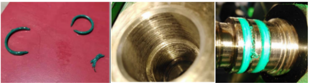
Damage Cause: The continuous rotation and rubbing of the O-ring against the sealing surface during the screwing-in of joint threads resulted in excessive wear, puncture injury from burrs, and fatigue fracture of the O-ring.
Figure 3 displays the steel seal on the air side of machine 2, which contains three uneven bumps and a leak that occurred during one week of operation.
The O-ring design specifications necessitate a static sealing surface roughness ranging from Ra1.6 to Ra3.2. At the same time, the steel diaphragm must have a roughness of Ra0.4, and the high-pressure sealing surface can be appropriately improved. However, based on the processing accuracy observed on-site, it needs to meet the design specifications. Hence, during the procurement process, it is crucial to enhance the technical quality certification documents that bind the manufacturing plant and strictly scrutinize the quality acceptance during the manufacturing and processing stages to prevent issues such as open mold shrinkage crack, flying edge combination, excessive trimming, flow marks, dents, and non-standard sealing surface roughness.
Insufficient hardness and filling rate of O-ring
The diaphragm compressor of Machine 1 experienced a rapid increase in measured value growth rate for diaphragm rupture alarms, typically reaching 0.15 MPa within five days. To address this issue and reduce the need for frequent operation of the root valve by field personnel, the manufacturer redesigned the seal ring with improved filling rate and hardness requirements.
The original O-ring seal, provided by the manufacturer according to their internal standard, had a wire diameter of 5.3 mm, a filling rate of 87.5%, and a hardness of HA75. However, based on the specifications for O-ring seals and the usage scenario, the hardness needed to be increased from HA75 to HA90, and the filling rate required to be adjusted from 65% to 90%, given the characteristics of high-pressure pure hydrogen and easy permeability. While the original design met the specification requirements, it needed to be deemed more.
After the modification, the wire diameter was increased to 5.5 mm, the hardness was improved to HA90, and the filling rate reached 94%. The change effectively addressed the issue and enhanced seal leakage.
Impurities
Improper installation and irregular application of grease can lead to frequent leakage of O-ring seals. A small amount of compatible oil can be applied between seals to prevent it. However, avoiding grease-containing solid additives such as molybdenum disulfide or zinc sulfide is essential.
Temperature
The O-ring material currently selected for the diaphragm compressor is mainly NBR and FKM, as shown in Table 3, and the performance parameters can meet the production requirements. However, as shown in Table 2, seal failures and leakage are prone to occur during the sudden temperature drop from December to February in Guangzhou each year. Therefore, preventive maintenance can be carried out in advance during this period, and the sealing points can be tightened and calibrated using a regular torque wrench.
| Seal name | Temperature range/℃ | Use area | Features |
| Nitrile rubber(NBR) | -40~120 | Oil side | Oil resistant |
| Fluoroelastomer(FKM) | -20~204 | Gas side | Temperature, oil and chemical resistance |
| Perfluoroether rubber(FFKM) | -40~327 | Gas side | Best chemical resistance and high temperature resistance, but higher cost |
O-ring installation quality
Stretching O-rings excessively should be avoided during cleaning and installation as it can decrease the cross-sectional area and subsequent leakage. The O-ring design specifications dictate that the stretching amount should not exceed 1% to 5%, as even a 1% stretch can cause the cross-sectional diameter to decrease by approximately 0.5%.
Factors that damage the diaphragm
Materials
There are two diaphragm materials for diaphragm compressors: metal diaphragm and non-metal diaphragm. The material of the diaphragm should have a high elastic limit and fatigue limit. Currently, the most commonly used materials for hydrogen diaphragm compressors are 00Cr15Ni5, 316, 301, and others, and the typical service life of a metal diaphragm in the market is about 4,000 hours. To enhance the fatigue strength of the diaphragm, a metal diaphragm can undergo solid solution treatment followed by deep cooling processing treatment, resulting in a finer and denser microstructure and a substantial increase of 65 MPa in tensile strength for the 00Cr15Ni5 metal diaphragm. However, due to different treatment processes, there may be differences in the aging tensile strength of the metal diaphragm in actual applications.
According to Table 4, the 301 material has a high carbon content and hardness, with Ni content between 00Cr15Ni5 and 316. It has better fatigue resistance and is suitable for elastic use. The tensile strength can be significantly improved through cold working, making it a commonly used material. Furthermore, non-metallic diaphragms made of carbon fiber are also under research and testing.
| Brand | C/% | Si/% | Mn/% | Cr/% | Ni/% | S/% | P/% | Tensile strength/MPa |
| 00Cr15Ni5 | ≤0.07 | 0.27 | 0.22 | 14.92 | 5.24 | 0.002 | 0.006 | 611 |
| 316 | ≤0.08 | 1 | 1 | 16.0~18.5 | 10.0~14.0 | 0.03 | 0.035 | 520 |
| 301 | ≤0.15 | 1.0 | 2.0 | 16.0~18.0 | 6.0~8.0 | 0.03 | 0.045 | 520 |
Friction
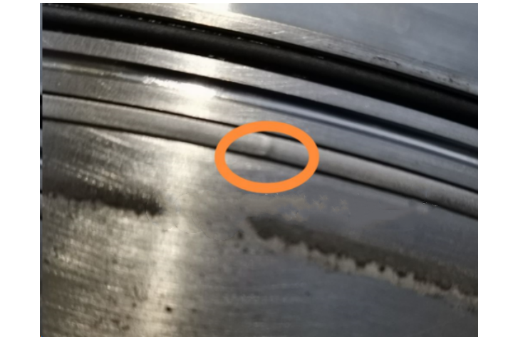
The sealing performance of the diaphragm head can be affected by the roughness of the diaphragm material, cylinder head, and oil distribution plate sealing surface. After forming, the diaphragm must undergo polishing to achieve a smooth and bright feeling. The manufacturer’s technical requirements state that the roughness of the diaphragm and sealing surface should be ≤ Ra0.4, but as shown in Figures 4, the actual material performance falls short of the relevant technical requirements. The manufacturer has provided polished diaphragms, but the operation cycle is yet to be observed.
To minimize the impact of friction on diaphragm life, the intermediate compressor diaphragms require special treatment. Depending on the working conditions, options such as lining TEFLON coating, brass material, etc., can be chosen. The same type of material diaphragms should have an appropriate amount of oil coating between the surfaces to reduce friction.
Stress
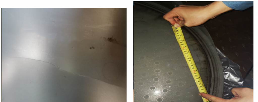
To enhance hydrogen production, it is necessary to maximize the diaphragm’s design deflection and ensure a reasonable stress distribution on its surface, which can reduce the peak stress curve and extend its lifespan. As observed from the location of diaphragm rupture shown in Figures 4 and 5, it occurs at approximately 85% to 90% of the radial dimension from the center to the edge.
Typically, the thickness of a steel diaphragm is maintained between 0.3~0.5 mm, as excessively thick diaphragms can lead to increased stress, while thinner ones may deform or fracture easily. A group of three diaphragms is clamped between the cylinder head and oil distribution plate, and incorrect installation can cause stress concentration in the diaphragm. Therefore, enhancing the surface finish of the diaphragm and sealing surfaces, along with the reasonable selection of O-rings, can significantly improve the equipment’s sealing performance. Moreover, reducing the preload of cylinder head bolts makes it possible to lower the additional stress on the diaphragm and extend its service life.
Media cleanliness
As per the Technical Specification for Safe Use of Diaphragm Compressor for Hydrogenation Station (T/CCGA 40004-2021), it is required to equip the compressor inlet and lubricating oil line with filters having a filtration precision of ≤25 μm. During actual operation, a five μm filtration accuracy inlet filter is installed at the gas source outlet and compressor inlet. A filter element with a filtration accuracy of 5 μm is also installed in the oil line. This installation satisfies the requirements for the stable, long-term operation of the equipment.
Temperature
The standard requirement for a “Diaphragm Compressor” (JB/T 6905-2019) states that the exhaust temperature of the compressor should not exceed 180 ℃. When the exhaust temperature is too high, it can reduce the diaphragm material’s performance and increase the diaphragm’s thermal stress. Additional water cooling facilities and interstage heat exchangers can be installed in the diaphragm head cylinder cover to address this issue. These facilities help to reduce the diaphragm head temperature and extend the diaphragm’s service life.
For units with interstage heat exchangers, it is essential to control the exhaust temperature according to Sinopec’s “Refining Process Corrosion Prevention Management Regulations” requirements. This regulation stipulates that the temperature of the process medium in the circulating cooling water heat exchanger should be less than 130 ℃. Maintaining this temperature helps to reduce the harmful effects of circulating water scale corrosion on the equipment.
Hydraulic oil
- Regulators
The hydraulic oil system plays a crucial role in ensuring the long-term operation of the diaphragm compressor. This system comprises a motor-driven crankshaft, connecting rod, crosshead, and a special piston that generates hydraulic oil pressure through the reciprocating motion of the piston. This pressure pushes the diaphragm on the oil side to the gas side, compressing and discharging the gas. The system also includes regulators, piston pumps, and check valves.
The regulator, installed on the diaphragm head, sets the hydraulic oil pressure that controls the diaphragm head discharge pressure. Typically, the force is charged 5% to 20% higher than the exhaust pressure. Currently, there are two types of regulators: fixed pressure and follower valve. The set pressure mode can adjust the pressure by turning the regulator handwheel, while the follower valve can regulate the diaphragm head oil pressure in real-time based on the gas-side inlet pressure changes.
During high-purity hydrogen charging, the compressor outlet and buffer tank pressures fluctuate significantly, ranging from 1.5 to 2.0 MPa. When using a fixed pressure regulator, these fluctuations can cause abnormal cylinder patting in the diaphragm head cylinder head. However, the follower valve, installed on the diaphragm head, has better pressure adaptability and is better suited for these operating conditions.
- Insufficient oil supply capacity of plunger pump
There are two methods of supplying oil to the diaphragm head: external and main oil pump supply at the shaft head. In July 2021, machine 2 experienced an interruption in diaphragm head oil return, leading to a secondary diaphragm rupture. Analysis showed that the cause was insufficient oil supply from the plunger pump at the secondary diaphragm head.
The equipment has a primary gear with 86 teeth, a speed increase gear with 24 teeth, and a main motor speed of 365 r/min. To improve the oil supply, the plan was to change the speed increase gear to 22 teeth. After the transformation, the oil volume increased by 2.9 L/min, and the operating parameters returned to normal.
Conclusion
Ensuring the stable functioning of a diaphragm compressor at a hydrogen refueling mother station is essential for cost control. In the event of a malfunction at your production facility, rest assured that our engineers possess the expertise and skills to resolve the issue. If you have any suggestions regarding equipment selection or enhancement, please visitour website and contact us at your convenience.
 Email
Email sales:+86 15366749631