During the operation of air compressors, the discharge of condensate is often overlooked but critically important. As ambient temperature, air humidity, and compressed air pressure fluctuate, significant amounts of moisture are continuously precipitated in the system. If improperly handled, this can lead to equipment corrosion and malfunction, severely compromising air quality, energy efficiency, and regulatory compliance. To ensure the long-term stable operation of compressed air systems and to guarantee operational safety and environmental friendliness, understanding the principles of condensate formation and discharge precautions is essential.
If condensate is not properly discharged during compressor operation, it can lead to equipment corrosion, reduced energy efficiency, lubrication failure, and air source contamination, compromising system stability and compliance. It is essential to understand the mechanisms of condensate formation and to follow standardized procedures such as cooling preparation, controlled pressure relief, and measured drainage, supported by monitoring and main/backup system switching. A predictive maintenance mechanism should also be established to comprehensively improve operational efficiency, safety, and environmental standards.
I. Scientific Principles of Condensate Formation
1.1 Pressure Dew Point and Water Precipitation
Water vapor in compressed air condenses into liquid under certain conditions, and the Pressure Dew Point (PDP) is the key parameter in this transformation. When the air temperature drops below the PDP, vapor condenses into liquid. In a typical 7 bar (100 psi) system with an ambient temperature of 30°C and 80% humidity, ASME PTC-9 testing confirms condensate production can reach 45 ml/m³. In tropical regions, this is even more pronounced; for instance, a 75kW unit in a Southeast Asian factory can generate 55–75 liters of condensate per day. Accurate control of PDP and temperature monitoring enables effective prediction of condensate volume for subsequent management.
1.2 Three Key Formation Scenarios
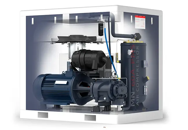
- Compression Phase: Air discharge temperatures can reach 180–200°C. The high-temperature air then enters an aftercooler, followed by initial separation in an air receiver tank, where large volumes of vapor condense into water.
- Shutdown Phase: When the unit shuts down, system cooling and pressure release reduce the air’s moisture-holding capacity, causing additional condensation.
- Low-Temperature Operation: When oil temperatures drop below 60°C (per ISO 8573-1:2023), low operating temperatures also promote condensate formation.These three scenarios cover the full operational and shutdown cycle and are the primary sources of condensate generation.
II. Seven System-Level Impacts
| Risk Type | Operational Impact | Economic Loss Model |
| Mechanical Failure | Rotor corrosion, bearing seizure | Repair cost ≈ 45% of equipment price |
| Energy Loss | 0.5 bar pressure drop = 7% efficiency loss | $1,200 annual loss for 37kW unit |
| Lubrication Failure | 80% viscosity drop (ASTM D445) | 60% reduction in oil change interval |
| Air Contamination | 300% increase in microbial growth (FDA 21 CFR 11) | 3–7% product defect rate |
| Safety Risk | 90% higher pipe freeze risk (≤0°C environment) | $7,000 loss per downtime incident |
| Regulatory Penalty | EPA Clean Water Act violations | 50,000 fines |
| Asset Depreciation | 35% shorter equipment life (ISO 5388) | 65% residual value loss |
Key Impacts:
- Corrosion & Failure: Repair costs up to 45% of equipment value.
- Energy Inefficiency: 0.5 bar pressure drop = 7% efficiency loss ($1,200/year for 37kW units).
- Regulatory Risks: Fines up to $50,000 for non-compliance with EPA standards.
III. Standard Operating Procedure (6-Step Method)
Step 1: System Preparation
- Cool the system fully: Air receiver temperature ≤ 40°C (requires ≥4 hours of cooling).
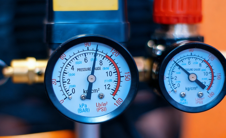
- Verify zero pressure on the dual-pointer pressure gauge.
- Use the MINNUO MN-HG85 wireless hygrometer to monitor ambient humidity for baseline data.
Step 2: Safety and Compliance
- PPE: Wear EN 374-certified nitrile gloves and ANSI Z87.1 safety goggles.
- Waste Collection: Use a UN-certified 20L water container.
- Lockout-Tagout: Comply with OSHA 1910.147 to prevent accidental operation.
Step 3: Controlled Pressure Relief
- Slowly open the exhaust valve to ≤30°, monitor pressure drop rate (≤0.5 bar/sec).
- Hold at stable pressure for 5 minutes per EN 1012-1 standards.
Step 4: Precision Drainage
- Adjust the ball valve to a 45° opening using a torque wrench (12–15 Nm / 9–11 lb·ft), maintaining a flow rate of 1.5 L/min.
- Close the valve when the oil-water ratio reaches 1:3 to avoid waste and environmental harm.
Step 5: Seal Verification
- Conduct a foam test per ASME B16.34: Apply a 3-second pressure-hold test.
- Acceptable pressure rise: ≤0.01 bar. Replace seals if leaks are detected.
Step 6: Digital Logging
- Scan and upload operational data to the MINNUO IoT platform for cloud storage.
- Automatic alerts trigger if deviations exceed 20%, enabling smart system management.
IV. MINNUO Dual-Mode Drainage System Technical Analysis
4.1 Primary Drainage System Features
- Sensors: Eight 316L stainless steel probes (±0.5 mm precision) for real-time water level monitoring.
- Valve Core: Self-cleaning nano-ceramic coating (tested 200,000 cycles to ISO 5208).
- Diagnostics: MTBF algorithms predict valve lifespan and alert for maintenance.
4.2 Backup System Design
- Redundancy: SIL-2 grade control for failover within 30 seconds.
- Piping: DN25 stainless steel increases flow capacity by 300%.
- Alerts: Real-time SMS/email notifications during faults.
V. International Compliance Framework
| Parameter | International Standard | MINNUO Solution |
| Oil Content | ISO 8573-1 Class 1 | Triple coalescing filter |
| pH Value | EPA 40 CFR 112 | Smart neutralization module |
| Suspended Solids | EU 2020/2184 | Centrifugal separation unit |
| COD | ISO 15705:2002 | Biodegradation module |
VI. Predictive Maintenance System
Maintenance Cycle (ISO 5388)
- Daily: IoT dashboard review of operational data.
- Weekly: Manual function tests for components.
- Monthly: Oil-water quality inspections (ASTM D7678).
- Quarterly: Air tank internal inspections (NACE SP0169).
Component Replacement Guidelines
| Component | Design Life | Warning Threshold |
| Solenoid Valve | 500,000 cycles | 450,000 cycles |
| Coalescing Filter | 8,000 hours | 7,200 hours |
| Dew Point Sensor | 5 years | 4.5 years |
VII. Conclusion
Condensate management in air compressors is critical for equipment longevity, operational efficiency, workplace safety, and regulatory compliance. Through scientific forecasting, standardized procedures, intelligent monitoring, and systematic maintenance, MINNUO provides a comprehensive, high-standard solution for condensate discharge. As intelligent manufacturing evolves, automated condensate management will drive businesses toward higher environmental and operational excellence.
 Email
Email sales:+86 15366749631