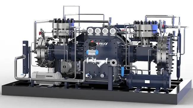
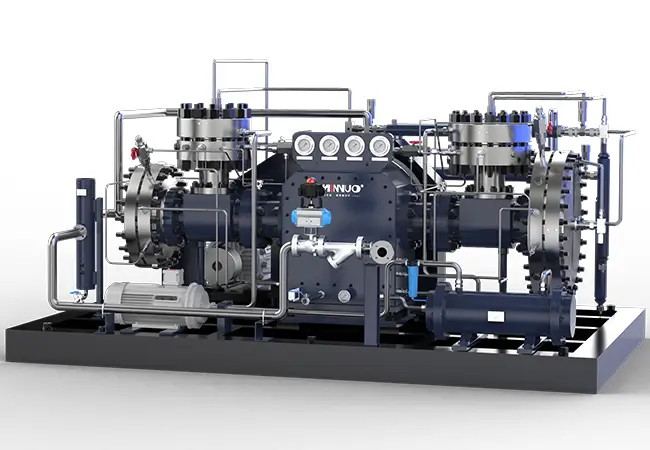
Diaphragm compressors are widely used in high-purity gas compression scenarios such as petrochemical, medical, and scientific research due to their excellent sealing performance and ability to avoid gas contamination. Their stable operation is crucial to ensuring continuous production in these industries. However, prolonged operation or improper handling may lead to equipment failures. Through regular maintenance and timely component replacement, most faults of diaphragm compressors can be effectively prevented and resolved. Based on MINNUO’s 30+ years of production and service experience, this article systematically summarizes the common faults and solutions of diaphragm compressors, and helps technical personnel quickly troubleshoot problems while ensuring efficient and stable operation of equipment by analyzing fault mechanisms and preventive measures.
Common faults in diaphragm compressors include diaphragm rupture or leakage, abnormal pressure output, excessive temperature rise, hydraulic system failure, abnormal noise or vibration, and control system faults. Solutions for these issues include diaphragm replacement, optimizing hydraulic system pressure, cleaning cooling systems, repairing oil pumps and pipelines, and adjusting the gaps between moving parts. Preventive measures such as regular inspections, monitoring system operating status, and updating key components can effectively avoid failures.
1. Diaphragm Rupture or Leakage
The diaphragm is a core component of the diaphragm compressor, and its integrity directly determines the device’s sealing and safety. Once the diaphragm ruptures or leaks, it not only causes gas contamination but may also trigger hydraulic system failures and even result in equipment shutdown.
1.1 Fault Symptoms
- Unstable or significantly reduced outlet pressure: After diaphragm rupture, the compression chamber cannot form an effective seal, causing gas leakage during compression, resulting in pressure fluctuations or failure to maintain the set value.
- Hydraulic oil mixed with compressed gas: The hydraulic oil chamber on both sides of the diaphragm connects to the gas chamber. Oil leaks through the rupture and contaminates the gas pipeline.
- Abnormal vibration or noise during operation: After the diaphragm tears, the balance of reciprocating motion is disrupted, causing mechanical vibration or abnormal noise.
1.2 Possible Causes
- Material fatigue or aging: The diaphragm bears high-frequency reciprocating stress for extended periods, and if the material lacks fatigue resistance, it can crack at weak points.
- Hydraulic system pressure exceeding limits: If the hydraulic oil pressure exceeds the design value, it causes the diaphragm to bear additional loads, leading to deformation and rupture.
- Gas contamination: The introduction of particles or corrosive substances into the medium can scratch or corrode the diaphragm surface.
1.3 Solutions
1.3.1 Diaphragm Replacement:
- Use OEM diaphragms: MINNUO diaphragms employ a multi-layer composite structure (e.g., metal + polymer), offering high tensile strength and corrosion resistance, ensuring compatibility with gas chemical properties.
- Standardize the installation process: Clean the compression chamber before installation to prevent particles from scratching the new diaphragm. When tightening bolts, apply force evenly in a diagonal sequence to avoid local stress concentration.
1.3.2 Optimize Hydraulic System Pressure:
Regularly calibrate hydraulic system pressure sensors to ensure they operate within the rated range (usually ±5% of the device’s nominal value). If frequent overpressure occurs, check the function of the relief valve or upgrade the hydraulic pump capacity.
1.3.3 Install Pre-Filter Devices:
- Install a filter with a precision of ≤10μm in the intake pipeline to capture solid particles.
- For corrosive gases (e.g., chlorine, hydrogen sulfide), use filter elements made from chemically inert materials (e.g., PTFE).
1.4 Preventive Measures
Perform non-destructive testing (e.g., ultrasonic inspection) on the diaphragm every 2,000 hours or six months (whichever comes first).
Establish a monitoring mechanism for the medium’s composition to avoid excessive gas impurities.
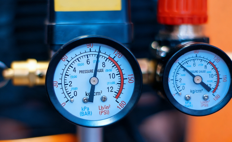
2. Abnormal Pressure Output
Abnormal pressure output is a typical problem in diaphragm compressor operation and may be caused by mechanical, hydraulic, or control system failures, requiring systematic troubleshooting.
2.1 Fault Symptoms
- Unable to reach set pressure: After long-term operation, the pressure remains lower than the target value.
- Pressure fluctuations: The pressure gauge needle frequently oscillates, exceeding the process’s allowable range (usually ±3%).
- Abnormal instrument readings: Pressure sensors malfunction or signal transmission is interrupted, leading to data distortion.
2.2 Possible Causes
- Pressure regulating valve failure: The valve core is stuck, the spring is ineffective, or the set value is shifted.
- Gas valve sealing failure: The intake or exhaust valve fails to close properly due to wear or carbon buildup.
- System leakage: Loose pipeline joints, aging seals, or cracked welds.
2.3 Solutions
2.3.1 Calibrate Pressure Regulating Valve:
- Disassemble the valve and clean the valve core and seat to remove oil or carbon deposits.
- Use specialized tools to reset the valve opening and verify the adjustment accuracy through pressure tests.
2.3.2 Repair Gas Valve Components:
- After disassembling the gas valve, check if the valve disk is deformed or worn. Minor defects can be repaired by grinding.
- If seriously damaged, replace the valve disk and spring. It is recommended to use MINNUO‘s OEM gas valve kits (with custom coatings that increase wear resistance by 30%).
2.3.3 Gas Tightness Test and Repair:
- Use a helium mass spectrometer or soapy water to test the pipelines, flanges, and welds comprehensively.
- For minor leakage points, temporary sealing with high-temperature sealant can be used, followed by immediate replacement of faulty seals.
2.4 Preventive Measures
- Test the functionality of the pressure regulating valve every quarter.
- Establish a gas valve maintenance schedule (recommended for repair every 4,000 hours).
3. Abnormal Temperature Rise
Abnormal temperature is an obvious sign of equipment overload or poor heat dissipation, which, if not handled in time, may lead to chain failures such as lubrication oil carbonization and bearing seizure.
3.1 Fault Symptoms
- Surface temperature exceeds limits: The compressor shell temperature exceeds 80°C (at an ambient temperature of 25°C).
- Lubrication oil high-temperature alarm: The oil temperature sensor triggers shutdown protection.
- Cooling system performance degradation: The cooling water outlet temperature difference is smaller than the design value (usually 5~10°C).
3.2 Possible Causes
- Cooling system blockage: Scaling in water-cooled radiators or dust buildup on air-cooled finned surfaces.
- Lubricating oil degradation: Oil oxidation increases viscosity, reducing fluidity.
- Worn moving parts: Excessive gaps in crankshaft bearings or connecting rod bushings lead to increased friction and heat generation.
3.3 Solutions
3.3.1 Clean the Cooling System:
- Water-cooled system: Use chemical descaling agents for circulation cleaning and install a soft water treatment device to prevent scaling.
- Air-cooled system: Use compressed air to reverse blow out the cooling fins and restore ventilation efficiency.
3.3.2 Replace Lubricating Oil:
- Use ISO VG68 grade synthetic lubricating oil, which has better high-temperature stability than mineral oils.
- When changing oil, completely drain the old oil and flush the oil circuit with new oil.
3.3.3 Check Moving Parts:
- Use an infrared thermal imager to locate high-temperature areas and dismantle and inspect components like bearings and piston rings.
- After replacing worn parts, readjust the fit gaps to the required specifications in the manual (e.g., crankshaft bearing gap of 0.05~0.10mm).
3.4 Preventive Measures
- Install an oil temperature monitoring device with multiple alarm thresholds.
- Perform a cooling system performance evaluation every six months.
4. Hydraulic System Failures
The hydraulic system is the power core of the diaphragm compressor, and its stability directly affects the equipment’s operational efficiency.
4.1 Fault Symptoms
- Oil pressure fluctuation or loss of pressure: The pressure gauge shows irregular jumps or drops to zero.
- Oil pump abnormal noise: Metallic friction sounds or cavitation noise occur during operation.
- Oil tank level anomaly: Significant short-term oil level drop (possibly accompanied by external leakage).
4.2 Possible Causes
- Hydraulic oil contamination: Particles entering the oil cause pump body wear or valve core sticking.
- Air entering the suction pipe: Filter blockage or poor sealing leads to cavitation.
- Seal aging: Hydraulic cylinder or joint seals fail, leading to internal or external leakage.
4.3 Solutions
4.3.1 Oil Purification and Replacement:
- Use an offline filtration unit to circulate the hydraulic oil (cleanliness should meet NAS 7 level).
- If the oil is emulsified or severely oxidized, it needs to be replaced entirely, and the oil tank cleaned.
4.3.2 Repair Oil Pump and Pipelines:
- Disassemble the oil pump to check for gear or vane wear. If the wear exceeds 0.1mm, replace the parts.
- Check for air leaks in the suction line and replace O-rings or hard pipe fittings as needed.
4.3.3 Upgrade Sealing Solutions:
- Use fluororubber seals (temperature range -20°C to 200°C).
- For high-pressure connections, use a double-seal structure (O-ring + combined gasket).
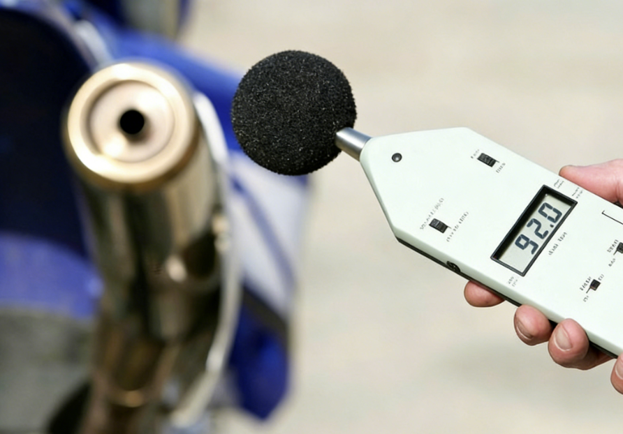
5. Abnormal Noise or Vibration Increase
Abnormal vibration not only affects the equipment’s service life but also poses a safety risk to operators. Immediate troubleshooting is required.
5.1 Fault Symptoms
- Mechanical impact sound: Periodic knocking sounds from the connecting rod, crosshead, and other areas.
- Foundation resonance: The equipment shakes, and anchor bolts become loose.
5.2 Solutions
5.2.1 Adjust Moving Parts Gaps:
- Use feeler gauges to check the gap between the crosshead and guide rails. If the gap exceeds 0.15mm, add adjustment shims.
- For excessively worn connecting rod bushings, replate or replace them.
5.2.2 Reinforce Equipment Foundation:
- Refill and fix loose anchor bolts using epoxy resin-based anchoring agents.
- Install vibration-damping rubber pads (damping coefficient ≥ 0.2) between the compressor base and foundation.
6. Control System Failures
Modern diaphragm compressors commonly use PLC control, which has high intelligence, but software and hardware failures may cause downtime.
6.1 Troubleshooting Process
- Check fault codes: Use the HMI to retrieve historical alarm records and locate the faulty module.
- Signal loop detection: Use a multimeter to measure the sensor’s supply voltage (usually 24VDC ±10%).
- Program backup and restoration: Regularly back up the PLC program and restart or roll back to a stable version in case of abnormalities.
6.2 Maintenance Recommendations: Full Lifecycle Management
- Intelligent operation and maintenance system: Deploy the MINNUO iMaint remote monitoring platform for real-time analysis of equipment health.
- Spare parts strategic inventory: For consumables like diaphragms and seals, it is recommended to stock 120% of the annual demand.
- Custom training: MINNUO offers a three-level training system for operation, maintenance, and fault diagnosis, providing certification.
7. Conclusion
The stable operation of diaphragm compressors is crucial to ensuring continuous production. With over 30 years of industry experience, MINNUO has built a comprehensive solution of “equipment + service + digitization.” We are committed to creating maximum value for our customers. For technical support or equipment supply, please contact the MINNUO service team immediately!
 Email
Email sales:+86 15366749631