In the complex systems of modern industrial production, the stable operation of fluid delivery equipment is essential. However, even high-performance diaphragm pumps may encounter failures due to operational or environmental factors during long-term use. This article provides an in-depth analysis of common failure causes and solutions for pneumatic diaphragm pumps used with air compressors, helping you quickly locate problems and restore equipment performance.
Common issues with pneumatic diaphragm pumps include reduced flow rate, air valve freezing, air bubbles at the outlet, liquid leakage from the exhaust port, and abnormal valve noise. Solutions mainly involve reducing pump speed, preventing cavitation, selecting appropriate materials, enhancing sealing, and using a dry air source. With proper maintenance and reasonable selection, the stability and service life of the equipment can be significantly improved.
I. Overview of Pneumatic Diaphragm Pumps for Air Compressors
1.1 Working Principle
A pneumatic diaphragm pump uses compressed air as its power source. Its unique working mechanism makes it stand out in the field of fluid delivery. Inside the pump body are two symmetrical working chambers, each fitted with an elastic diaphragm that forms a variable-volume cavity with the pump body. When compressed air enters one chamber through the air distribution valve, it pushes the diaphragm to the opposite side, increasing the chamber volume and creating negative pressure. Liquid is then drawn in through the inlet check valve under atmospheric pressure. Simultaneously, the diaphragm on the opposite side moves in reverse via a connecting rod, decreasing its volume and pushing liquid out through the outlet check valve. As the air distribution valve continuously switches the airflow direction, the two chambers alternately perform suction and discharge actions, enabling continuous fluid transport.
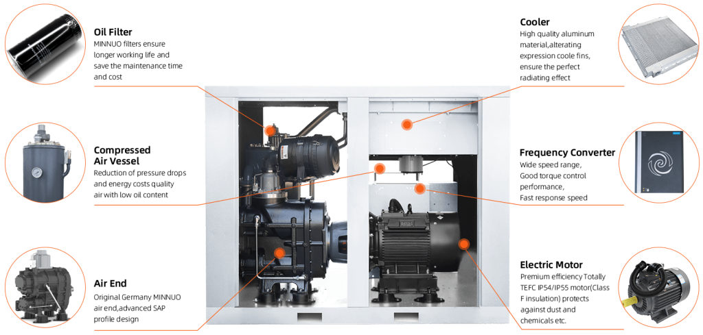
1.2 Core Advantages
1.2.1 Material Versatility
MINNUO pneumatic diaphragm pumps offer high flexibility in material selection. Pump bodies are available in plastic, aluminum alloy, cast iron, and stainless steel.
- Plastic: Lightweight and cost-effective, suitable for less corrosive fluids.
- Aluminum alloy: Combines light weight with good mechanical properties, ideal where weight is a concern.
- Cast iron: High strength, suited for high-pressure conditions.
- Stainless steel: Excellent corrosion resistance, widely used in chemical and food industries requiring strict hygiene and corrosion standards.Proper selection of pump materials ensures compatibility with diverse industrial conditions.
1.2.2 Corrosion Resistance Design
The diaphragm, a key component of diaphragm pumps, directly affects the pump’s ability to handle different media. MINNUO uses high-performance materials such as:
- Nitrile rubber: Good resistance to oil-based media.
- Fluororubber: Excels in heat and chemical resistance, suitable for strong acids and alkalis.
- PTFE: Exceptional chemical stability, capable of withstanding nearly all chemicals, including aqua regia, ensuring reliable transport of special media.
1.2.3 Zero Leakage Safety
Pneumatic diaphragm pumps lack traditional mechanical seals, eliminating leakage risks caused by seal wear. In industries like chemical and environmental protection, where media are often toxic, flammable, or explosive, leaks pose serious hazards. The zero-leakage design of MINNUO pumps ensures safety and meets strict safety and environmental standards.
II. Common Failure Causes and Solutions
2.1 Pump Operating But Flow Is Low or No Liquid Discharged
2.1.1 Cause Analysis
- Cavitation: Fast pump speed prevents fluid from fully filling the chamber, creating cavitation and reducing effective liquid transport.
- Stuck Valve Ball or Elastomer Swelling: Incompatible media cause chemical corrosion/swelling of diaphragms or valve balls, blocking flow (e.g., rubber deformation in organic solvents).
- Loose Inlet Fitting Causing Air Leak: Poor inlet sealing allows air intrusion, disrupting pressure and suction efficiency (e.g., loose clamps near valve balls).
2.1.2 Solutions
- Reduce Pump Speed: Adjust air intake flow/pressure to prevent cavitation.
- Inspect Valve Ball and Change Material: Regularly check for jamming/wear; use neoprene for oily media or PTFE for corrosive fluids.
- Re-tighten Inlet Clamp: Secure clamps (especially near valve balls) and apply sealant if needed.
2.2 Air Valve Freezing
2.2.1 Cause Analysis
Moisture in compressed air freezes at low temperatures, blocking air valves (common in winter or cold regions without air drying).
2.2.2 Solutions
Install air drying equipment:
- Refrigerated dryers: Cool air to condense moisture (dew point: 2–10°C).
- Adsorption dryers: Use desiccants (molecular sieves/activated alumina) for lower dew points (-40°C or below). Choose based on needs.
2.3 Bubbles at the Outlet
2.3.1 Cause Analysis
- Diaphragm Rupture: Chemical/mechanical stress causes diaphragm tears, mixing air with liquid.
- Loose Liquid Chamber Clamp: Poor sealing allows external air into the liquid chamber.
2.3.2 Solutions
- Disassemble and Replace Diaphragm: Check for damage; use fluororubber/PVDF for durability.
- Re-tighten Chamber Clamp: Ensure even and secure tightening to maintain sealing.
2.4 Liquid Leaks from Air Exhaust Port
2.4.1 Cause Analysis
- Diaphragm rupture or loose clamping plates allow liquid to enter the air chamber and exhaust.
2.4.2 Solutions
- Replace diaphragm and verify plate/shaft tightness using proper tools.
2.5 Abnormal Valve Noise (“Clicking”)
2.5.1 Cause Analysis
Insufficient inlet/outlet head causes valve balls to collide with seats due to low flow resistance, creating noise and accelerating wear.
2.5.2 Solutions
Improve pipeline pressure balance by increasing head (adjust layout, lengthen pipes, or add throttling valves). Avoid excessive head to prevent pump overload.
III. Safe Disassembly and Assembly Guide
3.1 Pre-Operation Guidelines
- Disconnect Air Supply and Relieve Residual Pressure: Shut air valve and open exhaust to release internal pressure to zero.
- Drain Liquid into Safe Container: Prevent pollution and contact with harmful media.
3.2 Disassembly Steps
- Mark Chamber Positions: Label left/right air/liquid chambers for correct reassembly.
- Remove Inlet/Outlet Pipes and Inspect Valves: Loosen bolts/clamps; check valve balls/seats for wear/corrosion.
- Separate Liquid Chamber and Center Body: Carefully remove bolts to avoid seal damage.
- Extract Diaphragm and Plate Assembly: Inspect components and prepare replacements.
3.3 Assembly Key Points
- Reverse Installation Order: Ensure proper placement and fit during reassembly.
- Use Compatible Lubricants: Apply silicone grease on seals to reduce friction, improve sealing, and prevent leaks (spread evenly).
IV. MINNUO Diaphragm Pump Maintenance Recommendations
4.1 Regular Inspection Schedule
- Every 500 Hours: Check diaphragms, valve balls, and valve movement for damage/aging.
- Every 2000 Hours: Replace diaphragms, valve balls, and seals (even if intact) to maintain performance.
4.2 Environmental Adaptation
- High-Temperature Conditions: Use stainless steel bodies and fluororubber diaphragms.
- Highly Corrosive Media: Opt for PTFE components for extreme chemical resistance.
4.3 Professional Support
MINNUO provides comprehensive technical support, including selection, installation, and after-sales maintenance. Our team offers customized solutions for consultation, commissioning, fault diagnosis, and repairs to ensure optimal equipment performance.
V. Conclusion
Industrial environments are complex and variable. If problems persist after troubleshooting, contact the MINNUO technical support team for expert diagnostics. Choosing MINNUO pneumatic diaphragm pumps ensures efficient, safe, and reliable fluid delivery.
 Email
Email sales:+86 15366749631