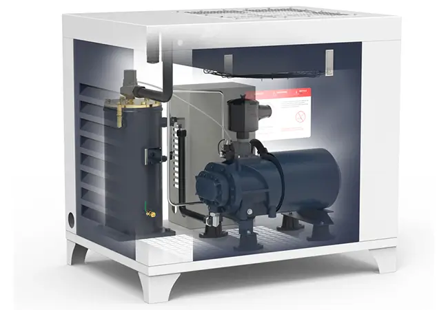
In industrial production systems, the air compressor serves as a core power device. Its stable and efficient operation directly impacts a company’s energy consumption and production efficiency. As equipment ages or production scales adjust, many enterprises face challenges due to insufficient air supply. However, modification is not simply an upgrade—reckless changes may trigger equipment failure and increased energy consumption. This article systematically analyzes three safe and reliable airflow enhancement methods, helping enterprises achieve increased airflow and optimized energy consumption at minimal cost.
The three airflow enhancement methods for air compressors include increasing speed, optimizing impeller structure, and adjusting intake air parameters. Increasing speed yields quick results at a low cost but has limited applicability. Impeller structure optimization involves higher technical requirements and delivers long-term energy savings. Intake parameter adjustment carries low risk and suits rapid retrofitting. When applied in combination, these methods can increase airflow by 15%–30% and reduce energy consumption by more than 20%.
1. Increasing Speed: The Most Direct Airflow Enhancement Strategy
1.1 Correlation Between Speed and Performance Curve
The compressor performance curve is a key chart illustrating operating characteristics (Figure 1). According to similarity laws, speed (n) is positively correlated with flow rate (qms) and pressure (Pr). When speed increases from n to n’, the performance curve shifts right along the x-axis, with flow rate increasing from qms to qms’. For instance, in a machinery manufacturing plant, increasing gearbox speed ratio by 15% resulted in a 12% rise in airflow without causing system pressure fluctuations, thereby ensuring production stability.
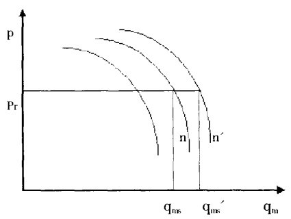
(Figure 1)
In practice, speed ratio adjustment can be achieved by replacing the gearbox or using a variable frequency drive (VFD). However, it is crucial to ensure that the increased speed is precisely matched with motor power to avoid overload risk. After adjustment, bearing load and vibration levels at the new speed must be thoroughly tested. If bearing temperatures exceed 80°C or vibration velocity RMS exceeds 4.5mm/s, root causes must be identified and corrected immediately to prevent equipment fatigue or failure.
1.2 Risk Control and Applicable Scenarios
This method has significant advantages: a short modification cycle (typically 3–5 working days) and relatively low cost, with investment mainly in gearbox or VFD replacement. However, its applicability is limited to compressor models with existing design margins for speed increase. Continuous overspeed operation accelerates bearing wear and shortens service life, so a single speed increase should be limited to 10%–15%.
A certain automotive plant increased compressor speed by 8% via VFD. Calculations show annual electricity savings exceeding RMB 200,000, and the modification cost was recovered within six months, demonstrating the method’s value in short-term efficiency improvement.
2. Impeller Structure Optimization: A Core Technology for Efficiency Improvement
2.1 Improvement of Meridional Plane at Impeller Inlet
Airflow turning in the impeller inlet area often causes flow separation and efficiency loss. Optimizing hub ratio (d/D), blade inlet diameter, and shroud curvature can effectively improve the flow field. Reducing hub ratio broadens the flow passage and lowers Mach number at the inlet; reducing hub ratio from 0.4 to 0.3 can decrease airflow loss by around 8%. Increasing blade inlet diameter buffers airflow impact—one engineering case showed this raised compressor efficiency by 5%. A gradient curvature shroud design further reduces boundary layer separation, enhancing intake efficiency.
2.2 Precision Design of Blade Geometry Parameters
Blade geometry directly determines compressor performance. Based on the empirical formula β1 = arctan (vu1/vm1), the airflow inlet angle (β1) is calculated, followed by adjusting installation angle (β = β1 + i), where incidence angle i must reflect actual working conditions. In one centrifugal compressor case, adjusting the incidence angle from +3° to –2° moved the surge boundary 10% to the right, greatly enhancing operational stability.
With CFD technology, 3D blades can be spatially twisted, and compared to traditional 2D blades, tests showed an 8% efficiency improvement. Blade count is also key: too few blades cause excessive diffusion angle and vortex formation, while too many increase friction loss. Practice suggests 8–12 blades as optimal.
2.3 Impact of Outlet Parameters on Performance
The outlet width ratio (b/D) and impeller outer diameter significantly affect compressor performance. Increasing outlet width reduces expansion losses, but must be balanced with leakage risk. The recommended outlet width ratio is 0.08–0.12. Increasing impeller outer diameter by 10% can raise outlet pressure by 15%, but rotor dynamics must be rechecked to ensure at least 20% safety margin between critical and operating speeds.
In one chemical plant, retrofitting the compressor with 3D impellers increased isentropic efficiency from 78% to 85%, saving over RMB 500,000 annually in electricity—highlighting the long-term energy-saving potential of impeller optimization.
3. Intake Air Parameter Adjustment: A Low-Risk Efficiency Enhancement Path
3.1 Effects of Temperature and Density
According to the ideal gas law ρ = P/(R・T), air density (ρ) is inversely related to temperature (T). Reducing intake temperature from 35°C to 20°C increases air density by around 5%, leading to a corresponding rise in mass flow rate.
To control temperature, evaporative coolers or other pre-cooling devices can be installed. Such investments usually recover within a year. Intake position should also be optimized to avoid drawing air from hot equipment zones. One textile plant increased airflow by 3% through this measure.
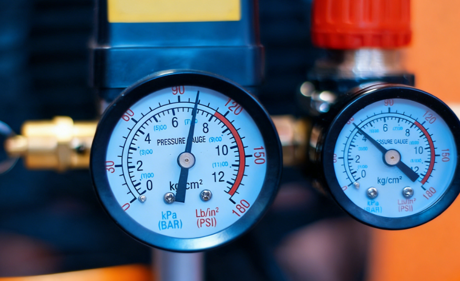
3.2 Pressure and Filtration System Optimization
Reducing intake resistance significantly improves flow rate—every 1 kPa reduction in pressure loss can raise flow by 0.5%. It is recommended to use low-resistance H13 filters and maintain them regularly. Additionally, installing a dryer to control humidity prevents condensation, which can reduce actual air supply. Caution is required, however—excessive cooling may lead to condensate freezing, requiring heat tracing or other anti-freezing measures.
4. Integrated Retrofit Plan and Cost-Benefit Analysis
4.1 Synergistic Application of Multiple Methods
A single modification often has limitations, while combining multiple methods maximizes benefits. A food processing plant adopted a “VFD + impeller optimization + intake cooling” solution, increasing airflow by 22% and reducing energy consumption by 18%, improving both production efficiency and cost control.
4.2 Retrofit Investment Evaluation
| Retrofit Method | Cost Range (RMB 10,000s) | Payback Period (Months) |
| Increasing Speed | 5–15 | 6–18 |
| Impeller Optimization | 20–50 | 12–24 |
| Intake Parameter Adjustment | 10–30 | 8–15 |
5. Frequently Asked Questions (FAQ)
Q1: Will airflow enhancement retrofits void the compressor’s warranty?
A: MINNUO provides certified retrofit services that strictly adhere to original factory technical specifications, ensuring that equipment warranties remain valid post-modification.
Q2: How to determine which method should be prioritized?
A: It is recommended to commission a professional agency to conduct an energy efficiency audit. Priority should be given to projects with shorter payback periods, such as intake cooling. For older equipment, impeller optimization may yield more significant long-term benefits.
6. Conclusion
Airflow enhancement for air compressors is a systematic project requiring controlled risk for maximum benefit. Relying on strong technical expertise, MINNUO offers a comprehensive “Diagnosis – Design – Implementation – Monitoring” service process, ensuring airflow increases of 15%–30% and overall energy efficiency improvement of over 20%. For customized retrofit solutions, feel free to contact our technical team and embark on a new journey of energy savings and efficiency gains!
 Email
Email sales:+86 15366749631