Electrolyzers produce hydrogen at pressures ranging from atmospheric to 30 bar—far below the 350-700 bar required for vehicle refueling or the 30-100 bar typical of pipeline injection. Bridging this pressure gap requires compression. But compressing hydrogen from an electrolyzer presents unique challenges: variable output matching renewable power, ultra-high purity requirements for fuel cell applications, and the need for oil-free compression to avoid contaminating downstream catalysts. Selecting the right hydrogen compressor for electrolyzer service demands understanding these specific constraints.
I. Electrolyzer Outlet Pressure and Hydrogen Quality
Different electrolyzer technologies deliver hydrogen at distinct pressure and purity conditions that directly influence compressor selection.
1. Alkaline Electrolyzers
Traditional alkaline electrolyzers typically operate at atmospheric pressure or low pressure up to 10-15 bar. Some advanced alkaline designs achieve 30 bar outlet pressure, reducing downstream compression requirements. The hydrogen produced is saturated with water vapor and contains trace oxygen and alkali aerosol (KOH) that must be removed before compression.
2. PEM Electrolyzers
Proton exchange membrane electrolyzers routinely deliver hydrogen at 30 bar , with some designs reaching 50-80 bar directly. Higher outlet pressure reduces the compression ratio required downstream, potentially eliminating one stage of compression. PEM hydrogen contains water vapor and trace oxygen but no liquid electrolyte aerosol.
3. Solid Oxide Electrolyzers
High-temperature solid oxide electrolyzers produce hydrogen at near-atmospheric pressure. The hydrogen stream is hot (700-900°C) and requires cooling before compression. These systems are less common in commercial deployment but growing for industrial hydrogen production.
4. Hydrogen Purity Requirements by Application
| Application | Required Purity | Contaminant Limits |
| PEM Fuel Cell (Transport) | 99.97%+ (ISO 14687) | CO <0.2 ppm, S <0.004 ppm |
| Pipeline Injection | 95-99% typical | Varies by pipeline operator |
| Industrial Feedstock | 99.9%+ typical | Application specific |
| Hydrogen Refueling Station | SAE J2719 / ISO 14687 | Stringent contaminant limits |
Electrolyzer hydrogen typically meets fuel cell purity requirements for everything except water and oxygen. The compressor and downstream purification system must address these remaining contaminants.
II. Why Electrolyzer Hydrogen Compression Differs from Conventional Hydrogen Service
Compressing electrolyzer hydrogen introduces considerations distinct from refinery or chemical plant hydrogen compression.
1. Oil-Free Compression Is Mandatory for Fuel Cell Applications
Fuel cell catalysts are exquisitely sensitive to contamination. Even trace compressor lubricant reaching the fuel cell stack permanently degrades performance. ISO 14687 limits total hydrocarbons to <2 ppm. Oil-lubricated compressors with downstream purification can theoretically meet this limit, but the industry standard for electrolyzer hydrogen is oil-free compression —eliminating contamination risk at the source.
2. Variable Flow from Renewable-Powered Electrolyzers
When electrolyzers follow solar or wind power, hydrogen production fluctuates from zero to full capacity within minutes. The compressor must accommodate this turndown range without surge, overheating, or efficiency collapse. Fixed-speed reciprocating compressors struggle; variable-speed drives and capacity control systems are essential.
3. Water-Saturated Hydrogen
Electrolyzer hydrogen is saturated with water vapor. Compression increases the dew point, potentially condensing liquid water in intercoolers and discharge piping. Liquid water in compressor cylinders causes hydraulic lock and catastrophic damage. Adequate moisture separation between compression stages is non-negotiable.
4. Integration with Downstream Purification
Electrolyzer hydrogen requires drying and often oxygen removal before final use. Compressor selection must consider whether purification occurs before compression (protecting the compressor) or after compression (reducing purification equipment size). This trade-off significantly affects system design.
III. Compressor Technologies for Electrolyzer Hydrogen Service
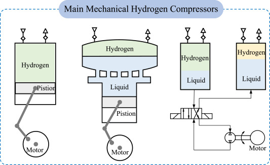
Four compressor types dominate electrolyzer applications, each with distinct advantages.
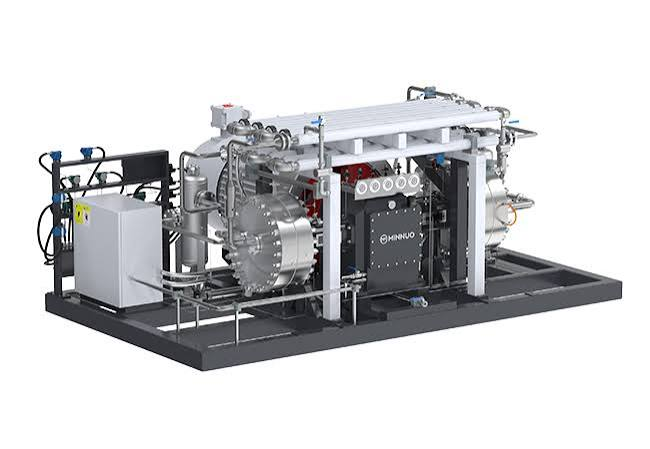
1. Diaphragm Compressors
Diaphragm compressors are the most widely deployed technology for electrolyzer hydrogen compression.
Advantages:
- Inherently oil-free: Process gas never contacts lubricant
- High purity preservation: Metal diaphragm isolates gas from hydraulic system
- High pressure capability: Up to 1,000+ bar in multi-stage configurations
- Proven reliability: Established technology with decades of hydrogen service
Limitations:
- Limited flow capacity: Maximum approximately 200 Nm³/hr per unit
- Diaphragm fatigue life: Requires replacement every 4,000-8,000 hours
- Higher capital cost than equivalent reciprocating compressors
- Sensitive to liquid water: Diaphragm rupture risk if water accumulates
Best fit: Flows up to 200 Nm³/hr, high-pressure applications (350-1,000 bar), fuel cell-grade hydrogen requiring absolute oil-free guarantee.
2. Hydraulic Driven Piston Compressors
Liquid-driven piston compressors use hydraulic oil to drive a free-floating piston, eliminating crankshaft and crosshead mechanisms.
Advantages:
- Oil-free gas end: Process gas contacts only piston rings and cylinder walls
- Higher flow capacity than diaphragm machines (up to 500+ Nm³/hr)
- Variable speed compatible: Hydraulic flow controls piston speed
- Compact footprint compared to traditional reciprocating compressors
Limitations:
- Ring wear particles enter hydrogen stream (though minimal)
- Higher maintenance than centrifugal machines
- Pulsation dampening required for downstream equipment
Best fit: Medium flows (100-500 Nm³/hr), pressures up to 500 bar, applications where minimal oil-free certification is acceptable but absolute zero-oil contact is not required.
3. Ionic Liquid Compressors
Ionic liquid compressors replace the metal piston with a column of ionic liquid—a molten salt with negligible vapor pressure.
Advantages:
- Near-isothermal compression: Ionic liquid absorbs compression heat, improving efficiency
- Zero metal-to-hydrogen contact in the compression chamber
- Self-lubricating: Ionic liquid provides sealing and lubrication
- Tolerates wet hydrogen: Liquid can absorb water vapor
Limitations:
- Emerging technology: Limited field experience and service network
- Ionic liquid cost and disposal: Specialized fluid requires periodic replacement
- Limited pressure capability: Currently demonstrated to 450-500 bar
Best fit: Applications prioritizing energy efficiency, wet hydrogen streams, and operators willing to adopt newer technology for efficiency gains.
4. Centrifugal Compressors
Centrifugal compressors serve very high-flow electrolyzer installations.
Advantages:
- Highest flow capacity: 1,000-100,000+ Nm³/hr
- Oil-free by design: Dry gas seals eliminate oil contact
- Low maintenance: Long continuous run times
- Smooth, pulsation-free discharge
Limitations:
- Limited pressure ratio per stage: Multiple stages required for high pressure
- Poor turndown: Narrow stable operating range
- High capital cost for small flows
- Surge risk during electrolyzer turndown
Best fit: Large-scale electrolysis (>50 MW), pipeline injection pressures (30-100 bar), steady-state operation rather than variable renewable power following.
IV. Compressor Configuration: Purification Before or After Compression?
The placement of hydrogen purification relative to compression affects both compressor protection and system cost.
1. Purification Before Compression
Drying and oxygen removal upstream of the compressor protects the compressor from moisture and oxygen effects.
Advantages:
- Compressor handles clean, dry hydrogen—longer component life
- Reduced corrosion and embrittlement in compressor internals
- No liquid water condensation during compression
Disadvantages:
- Purification equipment sized for low-pressure, high-volume flow—larger vessels and piping
- Higher capital cost for purification skid
- Pressure drop through purification reduces compressor suction pressure
2. Purification After Compression
Compression of wet electrolyzer hydrogen followed by purification at discharge pressure.
Advantages:
- Purification equipment sized for high-pressure, low-volume flow—smaller, lower cost
- Compressor delivers dry hydrogen directly to storage or dispensing
Disadvantages:
- Compressor exposed to wet hydrogen—increased corrosion and maintenance
- Liquid water knockout required between stages
- Diaphragm life reduced in diaphragm compressors handling wet gas
3. Hybrid Approach
Many systems employ partial treatment upstream—coalescing filtration and water knockout—with final drying and purification downstream. This balances compressor protection against purification equipment cost.
V. Sizing a Compressor for Electrolyzer Hydrogen
Proper sizing accommodates both nominal production and variability from renewable power.
1. Match Compressor Capacity to Electrolyzer Output
Electrolyzer hydrogen production at standard conditions is approximately:
H₂ Flow (Nm³/hr) = Electrolyzer Power (kW) × Efficiency (kWh/Nm³)
For a 1 MW PEM electrolyzer operating at 55 kWh/kg H₂ (approximately 4.9 kWh/Nm³): H₂ production = 1,000 kW ÷ 4.9 kWh/Nm³ = 204 Nm³/hr.
Compressor capacity must match this flow at electrolyzer outlet pressure. If the electrolyzer operates at 30 bar, the compressor inlet volume flow is significantly lower than the Nm³/hr value.
2. Account for Turndown Requirements
Electrolyzers powered by renewable energy operate across a wide load range—typically 10-100% of rated capacity. The compressor must accommodate this turndown without surge or inefficiency.
- Reciprocating/diaphragm: Variable speed drive, suction valve unloaders, or clearance pockets
- Centrifugal: Inlet guide vanes, variable speed, or recycle (inefficient)
- Multiple smaller units: Staging smaller compressors allows shutting down units at low flow
3. Staging for High-Pressure Applications
Compression from 30 bar to 900 bar requires multiple stages with intercooling. Typical configuration:
| Stage | Inlet Pressure | Outlet Pressure | Compression Ratio |
| 1 | 30 bar | 100-150 bar | 3.3-5:1 |
| 2 | 100 bar | 350-450 bar | 3-3.5:1 |
| 3 | 350 bar | 900 bar | 2-2.5:1 |
Intercooling between stages reduces power consumption and prevents excessive discharge temperatures.
4. Redundancy Considerations
Electrolyzer systems designed for continuous hydrogen supply often incorporate N+1 compressor redundancy. A single compressor failure stops hydrogen production; redundant capacity maintains output during maintenance.
VI. Integration with Downstream Hydrogen Systems
The compressor does not operate in isolation. Integration with storage and dispensing equipment affects overall system performance.
1. Buffer Storage Sizing
Low-pressure buffer storage between electrolyzer and compressor decouples electrolyzer output fluctuations from compressor operation. Buffer capacity typically sized for 15-30 minutes of electrolyzer production, allowing the compressor to operate at steady conditions rather than cycling with electrolyzer output.
2. Cascade Filling Coordination
For refueling station applications, the compressor fills high-pressure storage cascades (typically 350, 500, and 900 bar banks). Compressor controls must coordinate with cascade pressure sensors to direct flow appropriately and avoid short-cycling.
3. Heat Recovery Opportunities
Compression heat is valuable in electrolyzer systems. Intercooler heat can preheat electrolyzer feed water, improving overall system efficiency. This heat integration reduces the net energy penalty of compression.
4. Control System Integration
The compressor control system should communicate with the electrolyzer PLC and overall plant SCADA. Key signals include:
- Electrolyzer hydrogen flow rate and pressure
- Buffer storage pressure
- Cascade bank pressures
- Compressor health and maintenance alerts
FAQ
Q1: What is the typical energy consumption for compressing electrolyzer hydrogen?
A1: Compression from 30 bar to 900 bar consumes approximately 2.5-3.5 kWh/kg H₂, representing 5-7% of the electrolyzer energy input (50-55 kWh/kg). Each compression stage adds energy; optimizing intercooling and minimizing pressure drop improves efficiency.
Q2: Can I use a standard industrial air compressor for hydrogen?
A2: Absolutely not. Air compressors lack the material compatibility, sealing systems, and safety features required for hydrogen. Using an air compressor in hydrogen service creates severe embrittlement, leakage, and explosion hazards. Hydrogen compressors are purpose-built with hydrogen-compatible materials and safety systems.
Q3: How do I prevent water condensation during compression of wet electrolyzer hydrogen?
A3: Install high-efficiency moisture separators between compression stages. Maintain intercooler outlet temperatures above the dew point at that pressure. For diaphragm compressors, heat trace inlet piping to prevent condensation before gas enters the compressor. Consider upstream drying for critical applications.
Q4: What is the expected service life of a diaphragm compressor in electrolyzer service?
A4: Diaphragm life in hydrogen service typically ranges from 4,000 to 8,000 operating hours. Wet hydrogen and pressure cycling reduce life; clean, dry hydrogen and steady operation extend it. Scheduled diaphragm replacement is routine maintenance, not an indication of equipment failure.
Q5: How does variable electrolyzer output affect compressor efficiency?
A5: Fixed-speed reciprocating compressors lose efficiency at part load due to fixed mechanical losses and clearance volume effects. Variable-speed drives maintain better efficiency across the operating range. For highly variable renewable-powered electrolyzers, multiple smaller compressors may provide better overall efficiency than a single large machine operating at low load.
Q6: Is a buffer tank required between electrolyzer and compressor?
A6: Not strictly required, but strongly recommended for systems with variable electrolyzer output. The buffer tank allows the compressor to operate at steady conditions rather than cycling with electrolyzer output, extending compressor life and improving efficiency. For steady-state electrolyzer operation, a small pulsation dampener may suffice.
Conclusion
Compressing hydrogen from electrolyzers requires matching compressor technology to the specific characteristics of the electrolyzer—outlet pressure, hydrogen quality, and production variability. Diaphragm compressors dominate fuel cell-grade applications where absolute oil-free operation is non-negotiable. Hydraulic driven piston machines offer higher flow capacity with minimal contamination. Emerging technologies like ionic liquid compressors promise efficiency gains for next-generation systems. Regardless of technology, proper integration with purification, buffer storage, and downstream equipment ensures reliable hydrogen delivery from electrolyzer to end use.
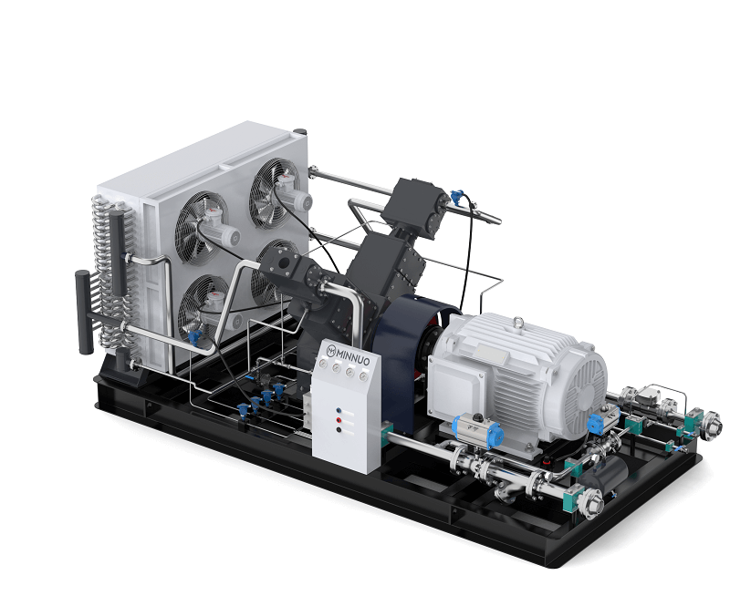
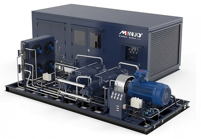
At MINNUO, we supply hydrogen compressor packages specifically configured for electrolyzer applications. Our systems accommodate the full range of electrolyzer technologies—from atmospheric alkaline to high-pressure PEM—with oil-free compression that preserves fuel cell-grade hydrogen purity. Every MINNUO hydrogen compressor includes material compatibility documentation, integrated safety systems, and warranty coverage for hydrogen service. Our engineering team provides system integration support to ensure seamless operation with your electrolyzer and downstream hydrogen equipment.
 Email
Email sales:+86 15312799623