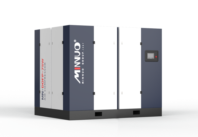
An industrial air compressor is a significant capital investment and the core utility of your production. A professional installation is not optional—it is the foundation of system reliability, energy efficiency, and long-term safety. A poor installation leads to chronic vibration, overheating, moisture issues, and premature failure, turning an asset into a constant source of downtime and cost.
This guide provides a structured, professional framework for plant managers, facility engineers, and maintenance leads to plan and oversee a correct industrial installation, ensuring your compressor delivers its full return on investment from day one.
Phase 1: Pre-Installation Planning & Site Assessment
Success is determined before the unit arrives on site.
Step 1: Location Selection & Environmental Control
- Ventilation & Cooling: The compressor must have an adequate supply of cool, clean air. Calculate the required ventilation rate; a rule of thumb is 3-4 m³/min of air per kW of motor power. Plan for separate, louvered intake and exhaust points to prevent hot air recirculation.
- Ambient Conditions: Maintain room temperature below 40°C (104°F). Install adequate lighting and ensure the floor is level, clean, and has a chemical-resistant coating with proper drainage for spills and condensate.
- Accessibility: Provide a minimum of 1 meter (3 feet) of clearance on all sides for routine maintenance, filter changes, and component replacement. Ensure doorways and paths can accommodate the delivery and future removal of major components.
Step 2: Foundation Design & Vibration Isolation
Industrial compressors require a stable, inert base.
- Consult Specifications: Follow the manufacturer’s requirements for foundation mass and bolt patterns.
- Standard Practice: For units up to 75 kW, a poured concrete inertia block (separate from the building floor) is often specified. For larger units, a full isolated foundation may be required.
- Isolation: Always use professionally specified vibration isolation pads or spring mounts between the compressor and the foundation. Never bolt the unit directly to the floor.
Step 3: Electrical & Power Supply Preparation (Critical)
This phase must be handled by a licensed industrial electrician.
- Review Nameplate: Provide the electrician with exact specifications: Voltage (e.g., 400V/3/50), Full Load Amps (FLA), and Motor Starting Code.
- Dedicated Circuit: Install a dedicated power line from the main distribution panel with a correctly sized disconnect switch, circuit breaker, and contactor. Oversize wiring to account for voltage drop over long runs.
- Protections: Ensure proper short-circuit, overload, and phase-loss protection are in place per local electrical codes (e.g., NEC, IEC).
Step 4: Compressed Air System Piping Design
Plan the downstream system before installing the compressor.
- Pipe Material: Use anodized aluminum, stainless steel, or certified thermoplastic piping systems. Avoid galvanized steel (corrosion) and PVC (shatter hazard).
- System Layout: Design the main header to slope downward 1-2% in the direction of airflow, with drip legs at all low points to collect condensate.
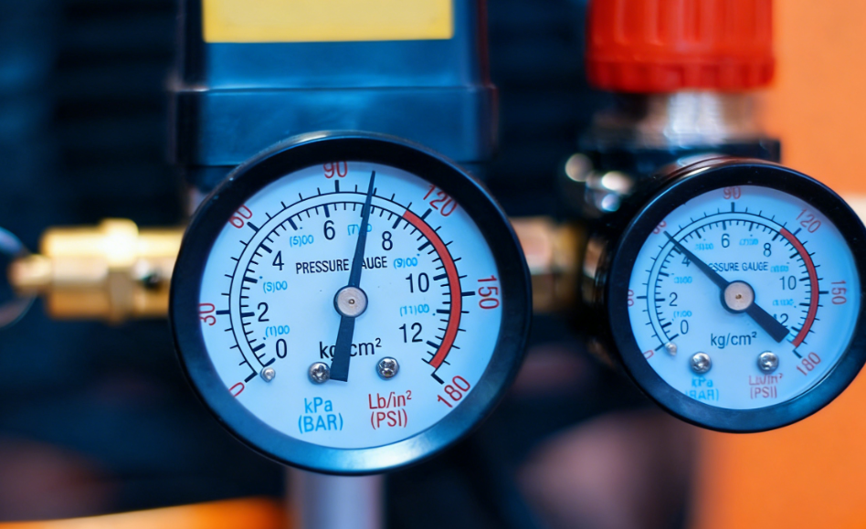
- Isolation & Drainage: Include a main isolation ball valve, a pressure gauge, and plan for automatic zero-loss drain valves at the tank and drip legs.
Phase 2: Installation & Mechanical Setup
Step 1: Receiving & Placement
- Use a forklift or overhead crane with appropriate capacity to move the unit. Do not drag or drop.
- Position the compressor onto the prepared vibration isolators.
- Use a precision level to ensure the unit is perfectly level in all directions. Shim the isolators as necessary. Misalignment causes excessive wear and oil carry-over.
Step 2: Initial Piping Connections
- Tank Outlet: Install a full-port ball valve directly on the tank outlet using appropriate sealant.
- Aftercooler & Dryer Connection: If separate, connect the aftercooler and air dryer following the manufacturer’s layout, ensuring proper drainage.
- Safety Valve: Verify the pressure relief valve on the tank is unobstructed and piped to a safe location if necessary.
Phase 3: First Startup & Commissioning Protocol
Follow this sequence meticulously. Do not start the compressor under load.
- Pre-Start Checklist:
- Confirm all shipping blocks, bracing, and protective covers are removed.
- Check all oil and coolant levels (per manufacturer specs).
- Ensure the electrical connections are tight and the rotation is correct (for three-phase motors).
- Fully open the main air outlet ball valve to allow an unloaded startup.
- Initial Run & System Check:
- Energize the power at the disconnect.
- Start the compressor and let it run unloaded for 15-30 minutes. Listen for abnormal noises (knocking, grinding, excessive vibration).
- Close the outlet valve and allow the system to build to cut-out pressure. Verify the automatic controls cycle correctly.
- Leak-Down Test & Inspection:
- Once the system is pressurized and shut off, apply a soap solution or ultrasonic leak detector to every connection from the tank outlet onward.
- A well-installed system should hold pressure for an extended period. A rapid drop indicates a significant leak that must be addressed.
- System Integration & Handover:
- Close the master valve and connect it to your pre-installed air distribution header.
- Document all readings (operating pressures, temperatures, amp draw) as a baseline for future maintenance.
- Ensure all safety procedures and maintenance schedules are handed over to the operating team.
Professional Mandates: When You Must Hire an Expert
This installation requires a professional team. Ensure you engage:
- A Licensed Industrial Electrician for all power connections.
- A Certified Rigging Crew for moving large units.
- A Piping Contractor experienced in compressed air systems for complex distribution networks.
- The Equipment Supplier or Manufacturer’s Technician for final commissioning and warranty validation, especially for large, variable-speed, or oil-free units.
FAQ: Professional Installation Concerns
Q1: What is the single most common installation mistake you see?
A1: Inadequate cooling airflow and hot air recirculation. This leads to chronic overheating, which is the primary cause of premature oil degradation, reduced capacity, and component failure.
Q2: How critical is the foundation? Can’t we just put it on the plant floor?
A2: Critical. Without a proper foundation and isolation, vibration transmits into the building structure, causing noise, loosening pipe connections, and leading to fatigue failures in the compressor itself. It is a non-negotiable best practice.
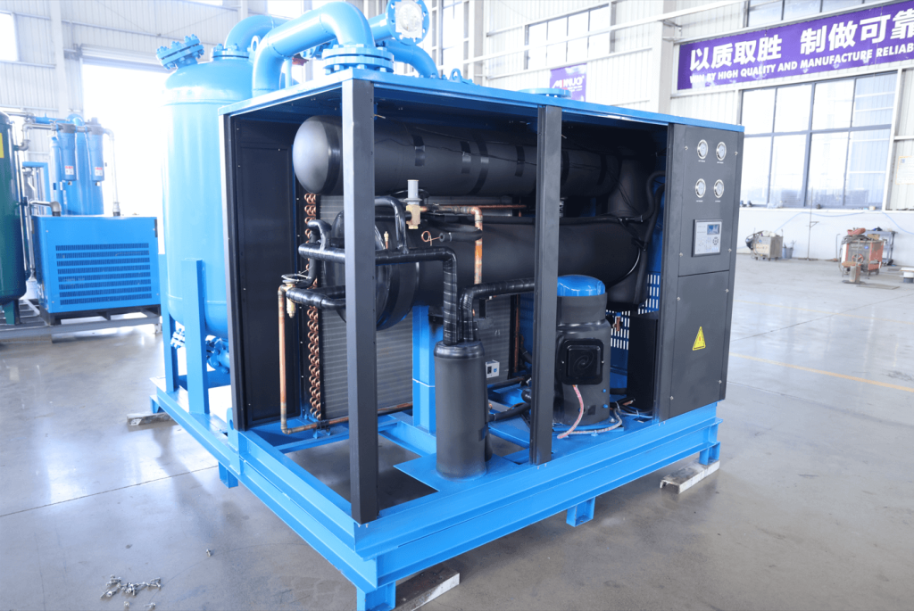
Q3: Should the air dryer be installed before or after the receiver tank?
A3: For a refrigerated dryer, install it after a “wet” receiver tank. The tank allows air to cool further, dropping out liquid water and reducing the load on the dryer. For a desiccant dryer, follow the manufacturer’s recommendation, but proper pre-filtration is essential in either case.
Q4: Who is responsible if something goes wrong during startup?
A4: Clear delineation is key. The installing contractor is typically responsible for mechanical and piping work. The electrician is responsible for power. The equipment warranty often requires startup by a factory-authorized technician to remain valid. Define these roles in your service contracts.
Conclusion: A Foundation for Performance
A professional air compressor installation is a systematic engineering project, not a simple equipment placement. By rigorously following these phases—meticulous planning, precise mechanical setup, and controlled commissioning—you transform a purchased asset into a reliable, efficient, and safe pillar of your production operations.
Cutting corners during installation guarantees higher lifetime costs. Doing it right from the start is the most economical choice.
Contact the MINNUO Engineering Team for project support. We can provide foundation drawings, electrical requirement specs, piping diagrams, and commission critical installations to ensure your system operates at its documented performance and efficiency.

 Email
Email sales:+86 15366749631