Diaphragm compressors are a particular type of reciprocating compressor. Unlike conventional piston compressors, they do not pressurize the gas directly through the reciprocating motion of a piston. Instead, they rely on the deformation of a diaphragm to change the cylinder’s volume. Their cylinders require no lubrication, and the compression medium never contacts any lubricant, so there is no contamination. Compression purity can reach 99.999%. Diaphragm compressors are often used to compress precious gases, or gases that are corrosive, radioactive, toxic or explosive — making them a mainstay of high-end industrial gas service. Below is a labeled diagram of the assembly, followed by the working principle step by step and the main types used in industry today.
Diaphragm Compressor Diagram
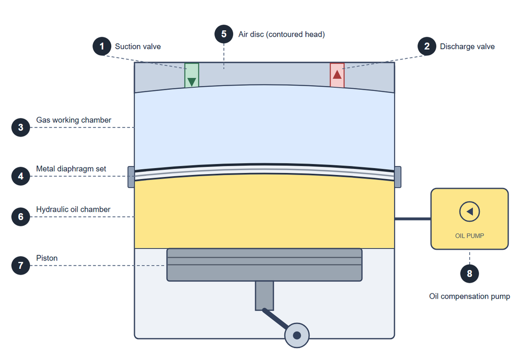
Diaphragm compressor diagram: 1 suction valve, 2 discharge valve, 3 gas working chamber, 4 metal diaphragm set, 5 air disc (contoured head), 6 hydraulic oil chamber, 7 piston, 8 hydraulic oil compensation pump
The diagram above shows the two chambers that define a diaphragm compressor. Everything above the diaphragm is gas; everything below it is hydraulic oil. The metal diaphragm set is the only part that touches both — and the only part that touches the process gas at all.
Working through the numbered parts:
- Suction valve — a spring-loaded automatic valve. It opens on the intake stroke, when chamber pressure falls below inlet pressure, and closes on the compression stroke.
- Discharge valve — the mirror of the suction valve. It opens only once chamber pressure exceeds line pressure.
- Gas working chamber — the sealed volume above the diaphragm. This is the volume that actually changes during the cycle.
- Metal diaphragm set — normally three layers: two outer barrier diaphragms plus an intermediate layer. The set is clamped at its edge by an O-ring seal and flexes without any sliding contact.
- Air disc (contoured head) — a machined plate shaped to match the diaphragm’s fully deflected position. It limits travel so the diaphragm cannot over-flex, and it defines the residual clearance volume.
- Hydraulic oil chamber — the space below the diaphragm. Piston motion displaces oil here, and that displacement is what moves the diaphragm.
- Piston — reciprocates inside the hydraulic cylinder, sealed by a piston ring.
- Hydraulic oil compensation pump — replenishes oil that has leaked past the seals. If this is neglected, oil volume drops, the diaphragm no longer reaches the air disc, residual volume rises and capacity falls.
The practical consequence of this layout is worth stating plainly: there is no packing, no lubricated bore and no sliding seal between the process gas and the outside world. Oil cannot reach the working chamber because the diaphragm set blocks it — which is where the contamination-free operation comes from.
What does “diaphragm” mean?
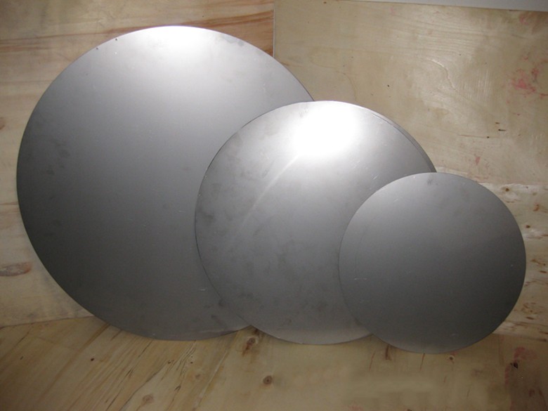
The diaphragm group is the critical component of a diaphragm compressor. It consists of two outer barrier diaphragms with an intermediate diaphragm between them. The group is fixed inside the cylinder by a seal, which divides the cylinder into two completely isolated parts — the working chamber and the hydraulic chamber. The diaphragm has good deformation capability and a long fatigue life. It flexes to change the volume of the process chamber, thereby pressurizing the gas. Diaphragms are usually made of rubber, plastic or metal; most diaphragm compressors use metallic diaphragms.
Diaphragm Compressor Working Principle (Step by Step)
A diaphragm compressor has two systems separated by a metal diaphragm: a hydraulic oil system and a gas compression system. Understanding the working principle means following one full cycle through both.
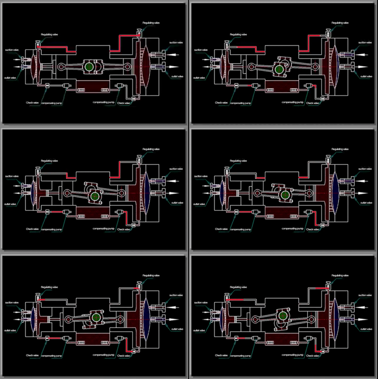
1. Intake. The piston in the hydraulic cylinder travels down. Oil pressure above the diaphragm drops, the diaphragm flexes downward, and the working chamber volume increases. Chamber pressure falls below inlet pressure, so the suction valve opens and process gas enters the chamber.
2. Hydraulic transfer. An electric motor drives the crankshaft, which drives the piston in a reciprocating motion through the drive train. The piston, sealed by a piston ring, moves back and forth in the hydraulic cylinder. Each piston stroke displaces a fixed volume of hydraulic oil.
3. Compression. As the piston travels up, it pushes oil against the underside of the diaphragm. The diaphragm deforms upward, the working chamber volume shrinks, and the trapped gas is compressed. Because the oil acts on the entire diaphragm face at once, the load is spread evenly rather than concentrated at a piston crown.
4. Discharge. Once chamber pressure exceeds line pressure, the discharge valve opens and the compressed gas leaves. The diaphragm presses up against the contoured air disc, which caps how far it can deflect.
5. Oil compensation. Throughout the cycle a small amount of oil leaks past the piston ring and seals, and it must be replenished continuously. If oil volume drops, the diaphragm no longer presses fully against the air disc, residual volume increases and compressor performance falls. Oil circuit compensation is therefore one of the maintenance items that most directly determines capacity.
One point that is easy to overlook: hydraulic fluid does three jobs here, not one. It transfers kinetic energy, it lubricates the moving parts, and it carries heat away — normally through a water-cooled cooler.
Why use diaphragm compressors?
Unlike conventional reciprocating compressors, a diaphragm compressor has a piston that moves inside a hydraulic cylinder. Each piston movement displaces a fixed volume of hydraulic oil, and that oil drives the diaphragm in a reciprocating motion. Because the oil acts on the diaphragm, it is the diaphragm — not the piston — that compresses the gas. This arrangement delivers several advantages.
- Complete isolation of gas from lubricant. The diaphragm separates the hydraulic oil from the working medium, eliminating the contamination path that exists in a conventional reciprocating compressor. Food, pharmaceutical and other industries with strict raw-material contamination control can use it with confidence.
- No sliding seal on the gas side. The diaphragm flexes rather than sliding against a bore. There is no packing and no piston ring exposed to the process gas — the reciprocating parts run in oil, on the other side of the diaphragm, where they cannot contaminate the medium.
- Easier temperature control. Because the hydraulic oil that drives the diaphragm is stored in the crankcase, a cooling system can act on it directly. This keeps working efficiency from dropping at high compression ratios.
- Smaller residual volume. The piston head of a traditional piston compressor is a rigid part and cannot fully conform to the top of the cylinder. The diaphragm, by contrast, changes shape to match the air chamber, minimizing the remaining clearance volume and improving efficiency.
Types of Diaphragm Compressors
Diaphragm compressors are usually described along three axes: how many compression stages they use, how many diaphragm heads they carry, and how the diaphragm is driven. Most selection mistakes trace back to the third one.
By compression stage: single-stage vs two-stage
A single-stage diaphragm compressor compresses the gas once — from inlet pressure to final pressure — in a single diaphragm head. It is simpler and less expensive, and it is adequate for moderate compression ratios such as gas transfer, cylinder filling and lower-pressure laboratory work.
A two-stage or multi-stage machine compresses the gas in stages, with intercooling between them. Because the near-isothermal compression advantage depends on removing heat as it appears, staging is how diaphragm compressors reach very high pressures — up to 200 MPa. Multi-stage units are the norm for hydrogen refuelling, high-pressure cylinder filling and supercritical fluid work.
By head configuration: single-head vs double-head
A single-head unit has one diaphragm head on one crank throw. A double-head (duplex) unit mounts a head on each side of the crankcase, so a single motor and crankshaft drive two heads 180° out of phase. Double-head machines roughly double the flow for the same footprint, and the opposed layout cancels much of the reciprocating imbalance — which is why they run noticeably smoother at the same displacement.
By drive method: motor-driven vs linear
This is the distinction behind most confusing search results, so it is worth being precise.
A motor-driven (rotary-to-reciprocating) diaphragm compressor — the type described on this page — uses a motor, crankshaft and piston to move hydraulic oil, and the oil moves the diaphragm. It is built for high pressure and industrial flow, and it is what people mean by a “metal diaphragm compressor.”
A linear diaphragm compressor uses no crankshaft at all. An oscillating electromagnetic armature drives the diaphragm directly, usually through a connecting rod, at mains frequency. Linear units are small, quiet, oil-free and inexpensive — they are the diaphragm pumps and micro-compressors found in medical devices, gas analysers, aeration and vacuum service.
The practical difference is one of scale. A linear diaphragm compressor is a low-pressure, low-flow device; a motor-driven hydraulic diaphragm compressor is a high-pressure machine. If your requirement is above roughly 1–2 MPa, you are in the second category — see our diaphragm air compressor range for pressures, flows and wetted materials.
By drive fluid: hydraulically driven vs mechanically driven
Almost all industrial diaphragm compressors are hydraulically driven, because oil is what makes it possible to pressurize a flexible element evenly and to reach very high pressure. A minority of small units are mechanically driven, where the connecting rod acts on the diaphragm through a rigid plate. Mechanically driven units are simpler, but they load the diaphragm unevenly and are limited in both pressure and diaphragm life.
Application Areas
A diaphragm compressor has good cylinder heat dissipation, operates close to isothermal compression, and can adopt a high compression ratio. It therefore covers a wide pressure range, up to 200 MPa. It is used mainly in specialist gas service — industrial gases, food, petrochemical, nuclear power, aerospace, military equipment and scientific research. It suits gases requiring high compression pressure, high purity, or leak-free handling of flammable, explosive or corrosive media: hydrogen, helium, argon, ethylene, fluorine, hydrogen sulfide, chlorine, silane and nitrogen trifluoride.
Major Components
As a reciprocating displacement compressor, a diaphragm compressor can be divided into three parts: the working chamber, the drive, and the body. Gas pressure is increased by single or multi-stage compression to meet process requirements for pressure, flow and temperature. The system mainly comprises the following components.
Main body
It generally consists of the body, the motor and the crankcase. During operation the main body must withstand the pneumatic and inertial forces of the piston and the moving parts, and it transfers all or part of the compressor’s weight to the base.
Cylinder
The cylinder is where the gas is compressed. Because it operates at high pressure and has a complex structure with varying heat-exchange direction, it carries demanding technical requirements.
Piston assembly
The piston assembly of a diaphragm compressor consists of a piston, piston ring, piston rod (or piston pin) and other parts. The piston and cylinder form the compression space. The reciprocating motion of the piston assembly is transmitted through the hydraulic oil to the diaphragm group, completing the gas compression cycle.
Diaphragm group
The diaphragm system is a three-layer structure: two outer barrier diaphragms plus an intermediate layer, sealed at the edge by an O-ring. The cylinder is thereby divided into a hydraulic oil chamber and a working gas chamber. Diaphragms are usually made of rubber, plastic or metal; most diaphragm compressors use metallic diaphragms.
Valves
The valves control intake and discharge. They open and close automatically under pressure difference and spring force — an automatic action valve. A valve usually consists of a valve seat, a plate and a spring. Valves directly affect compressor operation and are divided into suction (intake) valves and discharge (exhaust) valves.
Connecting rod
Connecting rods fall into two types based on big-end construction: split connecting rods and integral connecting rods.
Crankshaft
A split connecting rod is assembled around the crank pin and secured with connecting rod bolts. An integral connecting rod is used with eccentric crankshaft designs, where the stroke is twice the eccentric distance. Integral connecting rods are simple to build and easy to install, and suit small machines. Split connecting rods match the crank pin of the crankshaft and are used for long-stroke machines. The big end is fitted with a thin-walled bearing bushing to improve wear resistance.
In addition to the components above, a diaphragm compressor is equipped with a lubrication system, a cooling system and an electronic control system.
FAQ: Frequently Asked Questions About Diaphragm Compressors
1: What is a diaphragm compressor and how does it work?
A diaphragm compressor is a positive displacement compressor in which a flexible metal diaphragm, rather than a piston, compresses the gas. The diaphragm separates the gas working chamber from the hydraulic oil chamber beneath it. A motor-driven piston moves hydraulic oil, the oil deflects the diaphragm upward, and the changing chamber volume draws gas in through the suction valve and discharges it through the outlet valve. Because the process gas never contacts oil or a sliding seal, compression remains contamination-free.
2: What are the key advantages of diaphragm compressors over piston compressors?
Four advantages matter most.
- No sliding seal on the gas side — the diaphragm flexes instead of sliding against a bore, so there is no packing or piston ring exposed to the process gas.
- No oil contamination — the diaphragm set isolates the gas completely, which is why food, pharmaceutical and electronic-gas duty is routine.
- Easier temperature control — the hydraulic oil can be cooled in the crankcase, which holds efficiency at high compression ratios.
- Smaller residual volume — the diaphragm conforms to the contoured air disc, so clearance volume is lower than a rigid piston crown can achieve.
3: What industries use diaphragm compressors?
Diaphragm compressors serve industrial gas production, petrochemical and refinery duty, food and beverage including CO2, medical and pharmaceutical gas supply, hydrogen energy and fuel cells, semiconductor and electronics fab gas, nuclear power, aerospace and defence, and laboratory research. They are chosen wherever the gas is high-purity, flammable, explosive, toxic, corrosive or radioactive, or where leakage cannot be tolerated.
4: How do I maintain a diaphragm compressor for optimal performance?
- Monitor oil compensation first: leaked hydraulic oil must be replenished continuously, or the diaphragm will not reach the air disc and capacity will drop.
- Replace diaphragm sets on condition rather than only after failure.
- Inspect and clean suction and discharge valves.
- Check hydraulic oil condition and filter.
- Verify cooling water flow and temperature.
- Watch discharge pressure and temperature for drift — discharge temperature is the most useful early indicator of diaphragm or valve trouble.
See our guide to common faults and solutions for diaphragm compressors for the full diagnostic list.
5: What is the difference between a diaphragm compressor and a reciprocating compressor?
A diaphragm compressor is a type of reciprocating compressor; the difference lies in what does the compressing. In a piston compressor the piston itself compresses the gas directly in the cylinder, so a piston ring and a lubricated bore sit against the process gas. In a diaphragm compressor the piston drives hydraulic oil, and the oil deflects a metal diaphragm that compresses the gas. That intermediate hydraulic step is what isolates the gas from the lubricated mechanism. Piston machines generally win on flow and cost; diaphragm machines win on purity and leak-free operation at high pressure.