You installed an oil-free compressor and high-grade filters, yet your precision instruments still fail, or your painted surfaces show defects. This frustrating and costly scenario is common because clean compressed air is not achieved by purchasing a list of components; it is engineered through integrated system design.
Treating compressed air quality as an afterthought—simply “adding a filter”—is a recipe for inconsistent results, production downtime, and hidden costs. The international standard ISO 8573-1 provides the target, but hitting that target requires a deliberate, backward-designed approach from the point of use back to the air intake.
This guide provides that blueprint. We will move beyond component selection to explain how to specify, design, and validate a complete compressed air system that reliably delivers the purity your most critical processes demand.
Step 1: Define the Endpoint – Decoding ISO 8573-1
Your entire system design begins with a single, non-negotiable specification: the ISO 8573-1 purity class. This standard defines air quality using a classification code with three numbers, each representing the maximum allowable concentration for a specific contaminant.
Understanding the Classification Code: ISO 8573-1 Class A.B.C
- First Number (A) = Particle class (concentration and size distribution per cubic meter).
- Second Number (B) = Water class (pressure dew point in °C).
- Third Number (C) = Oil class (total oil content in mg/m³, including aerosol, liquid, and vapor).
A lower class number (e.g., Class 1) signifies a stricter, cleaner requirement than a higher number (e.g., Class 4). Your most sensitive downstream process or equipment dictates the required class. The table below translates common classes into practical requirements:
| ISO 8573-1 Class | Particle (A) | Water / Dew Point (B) | Total Oil (C) | Governs Your Choice Of: |
| e.g., Class 4.3.2 | General Limits | ≤ -20°C PDP | ≤ 0.1 mg/m³ | Refrigerant Dryer, Coalescing Filter |
| e.g., Class 2.4.1 | Strict Particle Count | ≤ +3°C PDP | ≤ 0.01 mg/m³ | High-Efficiency Filters |
| e.g., Class 1.2.1 | Very Strict Particle Count | ≤ -40°C PDP | ≤ 0.003 mg/m³ | Desiccant Dryer, Oil-Free Compressor or Vapor Removal |
| Class 0 | As specified by user (more stringent than 1) | As specified by user | As specified by user | Full System Design with Validation |
Key Takeaway: You cannot select the right dryer or filter until you know your target Water (B) and Oil (C) class values. This ISO classification is your project’s North Star.
Step 2: Reverse-Engineer the Treatment Train
With your target ISO 8573-1 class (A.B.C) defined, work backward to select each major component. This ensures every element contributes to the final result.
A. To Achieve the Dew Point (Water Class B): Select the Dryer
The Water class (B) value directly dictates dryer technology.
- For Water Class 4 or higher (e.g., B=4, +3°C PDP): A refrigerated dryer is typically sufficient.
- For Water Class 3 or lower (e.g., B=2 or B=1, -40°C PDP or below): A desiccant dryer is mandatory. A refrigerated dryer cannot reach these dew points.
B. To Achieve the Oil & Particle Purity (Oil Class C & Particle Class A): Design the Purification Chain
This is a multi-stage defense, starting at the source.
1. Source Control: The Compressor
- For Oil Class 1 or 2 (C ≤ 0.01 mg/m³): You have two paths:
- Path A (Technical Oil-Free): Use a true oil-free compressor (e.g., centrifugal, scroll). This eliminates liquid oil at the source but does not eliminate oil vapor from the atmosphere or hydrocarbon contamination from downstream piping.
- Path B (Treated Oil-Injected): Use a standard oil-lubricated compressor paired with a high-efficiency purification chain. This path often has a lower CAPEX but requires more careful downstream design.
2. Core Purification: The Filter Stack
Regardless of compressor choice, a staged filtration system is non-negotiable for protecting downstream equipment and polishing air to spec.
- Particulate Filters: Remove rust and pipe scale. Always use as a pre-filter.
- Coalescing Filters: The workhorse for removing liquid oil and water aerosols. Essential for achieving low oil classes (1, 2). Efficiency is rated at a particle size (e.g., 99.99% at 0.01 µm).
- Activated Carbon Filters: Required to remove oil vapor, the final contaminant. They are a consumable polisher and must be installed after a coalescing filter.
The Golden Rule of Order: Compressor → Aftercooler → Wet Receiver Tank → Particulate Pre-Filter → Dryer → Coalescing Filter → (Optional) Activated Carbon Filter → Dry Receiver Tank (if needed).

Step 3: Design the Distribution to Prevent Re-Contamination
A perfectly treated air stream can be ruined by a dirty or poorly designed piping network. This step ensures purity is maintained all the way to the point of use.
- Material: Use clean, non-corroding materials like aluminum fast-pipe or stainless steel. Avoid black iron or galvanized steel, which rust internally.
- Layout: Implement a loop system for main headers to ensure balanced pressure and minimize dead-ends where moisture can pool.
- Installation: Pipe mains with a 1-2% slope away from the air source, with automatic drains at all low points. Always use swan neck drops (taking air from the top of the main) to prevent liquid carryover into tool lines.
Step 4: Validate and Maintain the System
Design and installation are only half the battle. Verification and maintenance ensure long-term performance.
- Commissioning Validation: After installation, test the air at critical points of use.
- Use a dew point meter to verify Water class (B).
- Use an oil aerosol detector or test kit to verify Oil class (C).
- Use a particle counter to verify Particle class (A) (for critical applications).
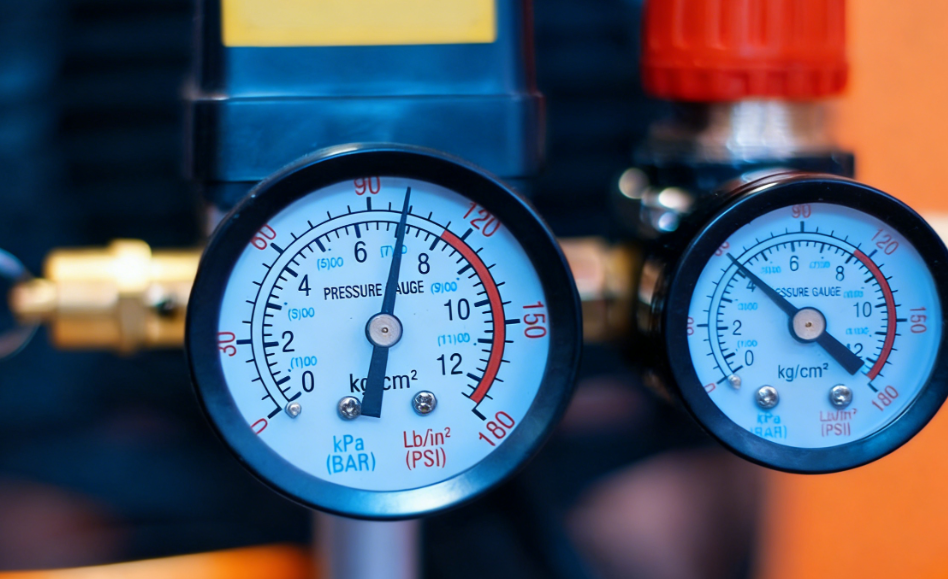
- Ongoing Monitoring: Install and monitor filter differential pressure gauges. Log dew point readings. Schedule regular filter element changes and desiccant replacement based on data, not just time.
- Periodic Re-Validation: Conduct annual air quality audits to ensure the system still meets the target ISO class as components age and plant demand changes.
Conclusion: Purity is a System Property
Achieving and maintaining ISO 8573-1 compressed air purity is an engineering discipline, not a procurement exercise. It requires:
- A clear specification (your ISO 8573-1 Class A.B.C).
- An integrated design (reverse-engineered component selection).
- A contamination-conscious installation (clean, dry piping).
- A culture of verification (trust, but measure).
Ignoring any one of these pillars will compromise the result and put your processes at risk. The investment in correct system design pays dividends in product quality, equipment longevity, and operational reliability.
For mission-critical air quality, the journey begins with a Compressed Air System Audit. At MINNUO, we start by measuring your current air quality and demand profile. We then develop a full system design—from intake to point-of-use—complete with component specifications and a validation plan, ensuring your investment is built on data and delivers guaranteed purity from day one.

 Email
Email sales:+86 15366749631