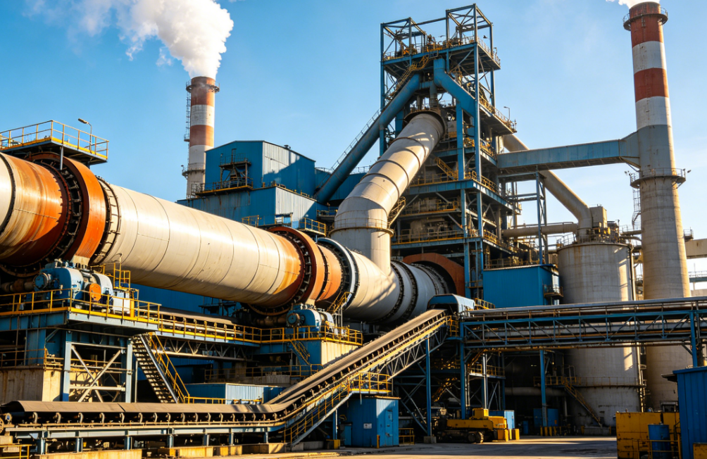
In modern industrial systems, screw air compressors have become indispensable air supply equipment. Therefore, any malfunction in a screw air compressor not only disrupts production rhythms but may also lead to safety issues and economic losses. Thus, an in-depth study of common faults and their solutions is crucial for ensuring the stability and efficiency of industrial production.
Common faults in screw air compressors include difficulty in starting, automatic shutdown, abnormal vibrations, and temperature anomalies. The main causes involve improper slide valve positioning, component wear, insufficient voltage, pipeline vibrations, and inadequate oil levels. Solutions include adjusting the slide valve, repairing or replacing damaged components, optimizing control systems, and ensuring sufficient lubrication and cooling.
1. Working Principle of Screw Air Compressors
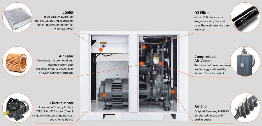
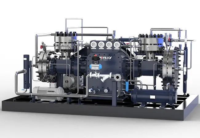
Screw air compressors mainly consist of a pair of intermeshing male and female rotors, a body, bearings, and seals. During operation, air enters the compressor through the intake port. As the rotors turn, the volume between the teeth continuously decreases, compressing the air and gradually increasing its pressure. Simultaneously, lubricating oil is injected into the compression chamber to lubricate, seal, and cool. The compressed oil-air mixture is separated by an oil-gas separator, with pure compressed air exiting through the exhaust port and the lubricating oil being filtered, cooled, and recycled. Understanding this working principle helps in more accurately analyzing the causes of faults.
2. Common Fault Types, Causes, and Solutions
2.1 Starting Faults
2.1.1 Excessive Starting Load or Failure to Start
A. Causes:
- Slide valve not at 0 position: Improper slide valve positioning increases starting resistance, leading to excessive starting load.
- Compressor filled with lubricating oil or liquid refrigerant: Excessive oil or refrigerant occupies compression space, making starting difficult.
- Component wear or burning: Wear or burning of moving parts disrupts normal fit, affecting starting performance.
- Insufficient voltage: Unstable power supply fails to provide adequate starting power.
- Excessive exhaust pressure: High exhaust pressure increases resistance during startup.
B. Solutions:
- Ensure the slide valve is at 0 position: Check and manually adjust if necessary before starting.
- Rotate the compressor to drain accumulated liquid or oil: Manually rotate the compressor to expel accumulated liquid or oil.
- Repair or replace worn components: Ensure normal operation by repairing or replacing worn or burned parts.
- Check voltage: Use a voltmeter to ensure voltage is within the rated range.
- Use a bypass valve to divert high-pressure gas to the low-pressure system: Open the bypass valve before starting to reduce exhaust pressure.
2.2 Operational Faults
2.2.1 Automatic Shutdown After Starting
A. Causes:
- Improper settings of automatic protection and control components: Incorrect settings cause the device to malfunction within normal operating parameters.
- Control circuit failure: Short circuits, open circuits, or component damage affect normal control.
- Overload: Prolonged high-load operation or sudden load increases exceed the device’s rated capacity.
B. Solutions:
- Check and adjust protection component settings: Adjust settings according to operational requirements.
- Inspect and repair control circuits: Perform a comprehensive check and repair or replace damaged components.
- Eliminate overload causes: Identify and address overload causes, such as adjusting loads or optimizing operational parameters.
2.2.2 Abnormal Vibrations
A. Causes:
- Loose anchor bolts: Loose bolts cause shaking during operation.
- Misalignment between compressor and motor: Misalignment causes imbalance and vibrations.
- Pipeline vibrations: Vibrations from pipelines can transfer to the unit.
- Excessive liquid refrigerant intake: Liquid refrigerant changes internal working conditions, causing vibrations.
- Unstable slide valve positioning: Unstable slide valves increase vibrations.
- High vacuum in the intake chamber: High vacuum affects normal operation, causing vibrations.
B. Solutions:
- Tighten anchor bolts: Regularly check and tighten bolts.
- Realign compressor and motor: Use professional tools for alignment.
- Adjust pipeline supports: Add or adjust supports to reduce vibrations.
- Adjust refrigerant supply: Control liquid refrigerant intake.
- Check oil pistons and load valves: Ensure stable slide valve positioning.
- Open intake stop valve: Adjust intake chamber vacuum.
2.2.3 Low Exhaust or Oil Temperature
A. Causes:
- Intake of wet vapor or liquid refrigerant: Affects heat transfer during compression, lowering temperature.
- Continuous no-load operation: Reduces heat generation, lowering temperature.
- Abnormally low exhaust pressure: Low pressure reduces energy conversion, lowering temperature.
B. Solutions:
- Reduce refrigerant supply: Adjust based on temperature changes.
- Check slide valve position: Ensure proper positioning.
- Reduce condenser capacity or water supply: Adjust condenser parameters.
2.2.4 Insufficient Cooling Capacity
A. Causes:
- Improper slide valve position: Affects compression ratio, reducing cooling capacity.
- Clogged intake filter: Restricts gas intake, affecting cooling.
- Machine wear: Increases gas leakage, reducing cooling capacity.
- High intake pipeline resistance: Affects gas flow, reducing cooling efficiency.
- Leaks in high/low-pressure systems: Causes cooling loss.
- Insufficient oil injection: Affects lubrication and cooling, reducing capacity.
- High exhaust pressure: Increases compression power consumption, reducing efficiency.
- Intake stop valve not fully open: Restricts gas intake, affecting capacity.
B. Solutions:
- Adjust slide valve position: Ensure proper positioning.
- Clean or replace intake filter: Ensure smooth gas intake.
- Repair or replace worn parts: Reduce gas leakage.
- Check intake pipeline valves: Ensure proper operation.
- Check bypass pipelines: Repair leaks.
- Check oil system: Ensure sufficient oil injection.
- Check exhaust system: Clean to reduce pressure.
- Ensure intake stop valve is fully open: Check and adjust.

2.2.5 Rapid Slide Valve Movement
A. Cause:
- Excessive manual valve opening: Increases hydraulic oil flow, causing rapid movement.
B. Solution:
- Adjust oil intake stop valve: Reduce flow to control movement speed.
2.2.6 Abnormal Noises During Operation
A. Causes:
- Debris in rotor grooves: Interferes with normal operation.
- Damaged thrust bearings: Increases friction, causing noise.
- Worn bearings: Affects stability, causing noise.
- Misaligned slide valve: Increases friction, causing noise.
- Loose moving parts: Causes shaking and noise.
B. Solutions:
- Inspect rotor and intake filter: Remove debris.
- Replace damaged bearings: Ensure smooth operation.
- Inspect slide valve guides: Ensure proper alignment.
- Disassemble and reinforce: Check and tighten moving parts.
2.2.7 High Exhaust Temperature
A. Causes:
- Excessive compression ratio: Increases temperature.
- High oil temperature: Affects heat dissipation.
- Intake of superheated vapor: Increases heat.
- Insufficient oil injection: Reduces cooling.
- Air in the refrigeration system: Affects operation.
B. Solutions:
- Reduce exhaust pressure and load: Adjust parameters.
- Clean oil cooler: Improve heat dissipation.
- Supply liquid to the evaporator: Adjust refrigerant supply.
- Increase oil injection: Ensure sufficient oil.
- Remove air and inspect components: Ensure proper sealing.
2.2.8 Stiff or Non-Moving Slide Valve
A. Causes:
- Faulty solenoid valve: Affects hydraulic oil control.
- Clogged oil pipeline: Hinders oil flow.
- Closed manual valve: Cuts off oil supply.
- Stuck or leaking oil piston: Affects slide valve movement.
B. Solutions:
- Repair solenoid valve: Ensure proper operation.
- Clean oil pipeline: Remove blockages.
- Open oil intake stop valve: Ensure oil supply.
- Repair oil piston: Ensure proper movement.
2.2.9 High Compressor Body Temperature
A. Causes:
- Severe intake overheating: Increases body temperature.
- Bypass pipeline leaks: Causes abnormal heat loss.
- Severe wear in friction areas: Generates heat.
- High compression ratio: Increases heat generation.
B. Solutions:
- Reduce intake superheat: Adjust refrigeration system.
- Inspect bypass pipeline and valves: Repair leaks.
- Repair or replace worn parts: Reduce heat generation.
- Reduce exhaust pressure and load: Adjust parameters.
2.2.10 Compressor Shaft Seal Leakage
A. Causes:
- Insufficient oil supply: Reduces sealing performance.
- Improper assembly: Causes leaks.
- Damaged O-rings: Loses sealing effect.
- Poor contact between moving and stationary rings: Causes leaks.
B. Solutions:
- Inspect oil supply system: Ensure sufficient oil.
- Reassemble or replace O-rings: Ensure proper sealing.
- Regrind moving and stationary rings: Improve sealing.
2.2.11 Low Oil Pressure
A. Cause:
- Clogged oil filters: Hinders oil flow.
B. Solution:
- Regularly clean or replace oil filters: Ensure smooth oil flow.
2.2.12 Slow or No Oil Return
A. Cause:
- Clogged or stuck oil return valve: Hinders oil return.
B. Solution:
- Disassemble, clean, and repair the oil return valve: Ensure proper operation.
2.2.13 High Oil Consumption
A. Causes:
- Clogged oil return filter or pipe: Affects oil return.
- Reduced oil separator efficiency: Increases oil loss.
- Excessive oil in the secondary oil separator: Affects operation.
- High exhaust temperature: Increases oil evaporation.
B. Solutions:
- Clean filters and oil return pipe: Ensure proper oil return.
- Replace oil separator core: Improve oil separation.
- Control oil level and reduce oil temperature: Reduce oil evaporation.
2.2.14 Rising Oil Level
A. Causes:
- Excessive refrigerant in oil: Increases oil level.
- Clogged oil separator outlet: Hinders oil discharge.
B. Solutions:
- Increase oil temperature: Accelerate refrigerant evaporation.
- Inspect and clean oil separator outlet: Ensure proper oil discharge.
2.2.15 Compressor Reversal During Shutdown
A. Causes:
- Faulty intake/exhaust check valve: Allows gas backflow.
- Clogged anti-reversal bypass: Causes reversal.
B. Solutions:
- Inspect intake/exhaust check valve: Repair or replace.
- Clean bypass and solenoid valve: Ensure proper operation.
2.2.16 High Compressor Intake Temperature
A. Causes:
- Insufficient refrigerant: Increases intake temperature.
- Clogged regulating valve or supply pipe: Affects refrigerant supply.
- Small regulating valve opening: Restricts refrigerant flow.
- Poor intake pipe insulation: Increases heat loss.
B. Solutions:
- Add refrigerant: Replenish as needed.
- Inspect regulating valve and supply pipe: Repair clogs or faults.
- Increase refrigerant supply: Adjust flow.
- Repair or replace insulation: Ensure proper insulation.
2.2.17 Low Compressor Intake Temperature
A. Causes:
- Excessive liquid refrigerant: Lowers intake temperature.
- Large regulating valve opening: Increases refrigerant flow.
B. Solutions:
- Reduce refrigerant supply: Adjust flow.
- Reduce regulating valve opening: Control flow.
2.2.18 High Condenser Pressure
A. Causes:
- Insufficient cooling water: Reduces heat dissipation.
- Condenser scaling: Reduces heat transfer efficiency.
- Excessive non-condensable gases: Increases pressure.
B. Solutions:
- Increase cooling water: Improve heat dissipation.
- Clean condenser: Remove scaling.
- Remove non-condensable gases: Use specialized equipment.
3. Daily Maintenance and Care for Screw Air Compressors
3.1 Lubrication System Maintenance
Regularly check oil level, quality, and cleanliness. Replace oil as per the manual to avoid wear due to aged or contaminated oil. Ensure oil filters are functioning and clean or replace them regularly.
3.2 Air Filter Maintenance
Clean or replace air filter elements regularly to ensure clean intake air and reduce wear. In dusty environments, shorten maintenance intervals.
3.3 Cooling System Maintenance
Keep cooler surfaces clean, remove dust and dirt, and improve heat dissipation. Check cooling water pump operation and ensure proper flow and pressure. Inspect cooling water pipelines for leaks.
3.4 Electrical System Maintenance
Regularly check electrical connections and cables for tightness and aging. Inspect electrical components like contactors and relays, and replace damaged parts promptly.
3.5 Regular Inspections
Establish a comprehensive inspection system. Have professionals regularly check operational parameters, vibrations, and noise to identify and address potential issues.
4. Fault Prevention Strategies
4.1 Optimize Operational Parameters
Adjust operational parameters like exhaust pressure, temperature, and flow based on production needs and equipment performance to avoid prolonged extreme conditions.
4.2 Personnel Training
Train operators on working principles, operational standards, and fault diagnosis. Ensure they can identify and report abnormalities and handle emergencies.
4.3 Establish Fault Warning Systems
Use advanced sensors and data analysis to create a fault warning system. Monitor operational parameters and states in real-time to provide early warnings and take preventive measures.
4.4 Rational Equipment Usage Planning
Plan equipment usage and loads based on production tasks and performance to avoid overuse and frequent starts/stops. Implement equipment rotation plans to extend lifespan.
5. MINNUO‘s Advantages
5.1 Product Advantages
- High Efficiency and Energy Saving: Advanced rotor design and optimized tooth volume ratio improve compression efficiency, saving 10%-15% energy. Efficient cooling and precise oil-gas separation further reduce energy loss.
- Stable and Reliable: Key components from international brands ensure high reliability and long lifespan. Strict quality control from raw materials to finished products ensures stable operation even in harsh environments.
- Intelligent Control: Advanced control systems offer remote monitoring, fault diagnosis, and automatic adjustment. Operators can view real-time parameters and receive fault alerts and solutions via SMS or email.
- Low Noise and Environmental Protection: Advanced noise reduction and soundproofing materials minimize noise. Efficient oil-gas separation ensures low oil content in compressed air, meeting environmental standards.
5.2 Service Advantages
- Pre-Sales Professional Consultation: Provide detailed technical consultation and tailored solutions based on customer needs.
- In-Sales Installation Services: Professional installation and commissioning by experienced engineers, followed by operator training.
- Post-Sales Timely Response: 24/7 customer service, regular follow-ups, and sufficient original spare parts for quick repairs.
6. Conclusion
Screw air compressor faults are complex and varied. In actual production, enterprises should prioritize maintenance and management, employing fault solutions, maintenance measures, and prevention strategies to reduce fault rates, improve operational efficiency, and ensure stable and efficient industrial production.
For more information, MINNUO welcomes your inquiries!
 Email
Email sales:+86 15366749631